
Page 50 - Mechanical Engineer's Data Handbook
P. 50
STRENGTHS OF MATERIALS 39
Resultant bending moments, M,: Driver
At any point M, = ,/-:
and the bending stress=M,fZ; Z=modulus
Resultant reactions, R, and R, (bearing loads):
A torque diagram is also drawn and the torque and
resultant bending moment can be found at any point.
The equivalent torque and equivalent bending mo-
ment are found as follows:
T, = Jw;
+
TJ2
Me
(M,
=
The shaft diameter is:
-
-
d=3 E ~rd-~ E (whichever is the greater)
where: T and o=the allowable shear and bending
stresses.
Note: bearings are assumed to act as simple supports.
1.6.2 ShdyI with gears and levers
Shafts with levers
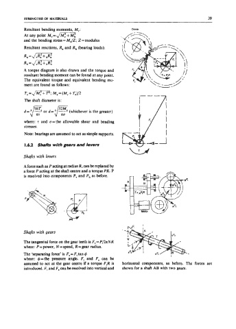
A force such as P acting at radius R, can be replaced by
a force P acting at the shaft centre and a torque PR. P
is resolved into components P, and P, as before.
Shafts with gears
The tangential force on the gear teeth is F, = Pf2zNR
where: P=power, N=speed, R=gear radius.
The ‘separating force’ is F, = F, tan &
where: &=the pressure angle. F, and F, can be
assumed to act at the gear centre if a torque F,R is horizontal components, as before. The forces are
introduced. F, and Fa can be resolved into vertical and shown for a shaft AB with two gears.