
Page 49 - Mechanical Engineer's Data Handbook
P. 49
38 MECHANICAL ENGINEER’S DATA HANDBOOK
Strain energy u = Cp;,J2E or Cfz;,J2G per unit volume
Type of spring Modulus Cf
Bar in tension or compression E 1 .o
Beam, uniform bending moment E 0.33
rectangular section
Clock spring E 0.33
Uniformly tapered cantilever E 0.33
rectangular section
Straight cantilever E 0.11
rectangular section
Torsion spring 0.25
Belleville washer 0.05 to 0.20
Torsion bar 0.50
to
Torsion tube i[l -(d/D)’] ~0.8 0.9
Compression spring O.SO/Wahl factor
1.6 Shafts
Rotating or semirotating shafts are invariably subject along the length of the shaft. The following shows how
to both torsion and bending due to forces on levers, the resultant bending moments and bearing reactions
cranks, gears, etc. These forces may act in several can be determined.
planes parallel to the shaft, producing bending mo- In the case of gears, the contact force is resolved into
ments which may be resolved into two perpendicular a tangential force and a separating force.
planes. In addition, there will be a torque which varies
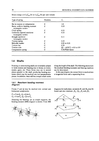
1.6. I Resultant bending moment
diagram
Forces P and Q may be resolved into vertical and diagrams for each plane, moments M, and M, may be
horizontal components: found and also reactions ,Ra, ,Rb, hRa and bRb.
P, = P sin Op, Q, = Q sin e,,
Ph= PCOS eP, Qh= Q Cos Os
Assuming the bearings act as simple supports, the
bending moment (BM) diagram is drawn. From BM yRa
hRa ++33th5