
Page 64 - Mechanical Engineer's Data Handbook
P. 64
STRENGTHS OF MATERIALS 53
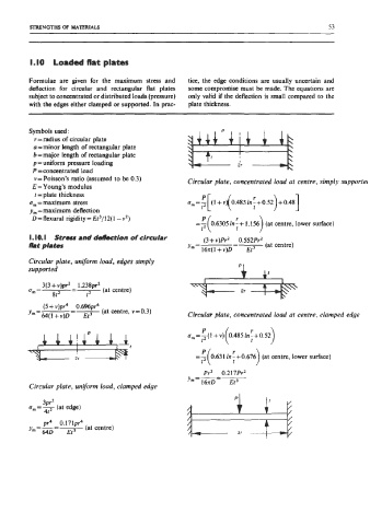
1.10 Loaded tlat plates
Formulae are given for the maximum stress and tice, the edge conditions are usually uncertain and
deflection for circular and rectangular flat plates some compromise must be made. The equations are
subject to concentrated or distributed loads (pressure) only valid if the deflection is small compared to the
with the edga either clamped or supported. In prac- plate thickness.
Symbols used: -
r = radius of circular plate
a = minor length of rectangular plate
b = major length of rectangular plate
p = uniform pressure loading ir -+
P =concentrated load
v = Poisson’s ratio (assumed to be 0.3) Circular plate, concentrated load at centre, simply supporter
E = Young’s modulus
t = plate thickness
u, =maximum stress
y, = maximum deflection
D=flexural rigidity= Et3/12( 1 -v2) r
(at centre, lower surface)
I. IO. I Stress ad ddlection of circular (3 + v)Pr2 0.552Pr2
(at centre)
lsht plates ym = 16n( 1 + v)D =F
Circular plate, uniform load, edges simply
supported
3(3 + v)pr2 1 .238pr2
U, = =- (at centre)
8t2 t2
(5 + v)pr4 0.6%pr4
’“=64(1 +v)D=r (at centre, v=0.3) Circular plate, concentrated load at centre, clamped edge
r
I I
I r
21 (at centre, lower surface)
Pr2 0.217Pr2
J ’ m = G = F
Circular plate, unform load, clamped edge
3pr2
0 =- (at edge)
In 4t2
pr4 0.171pr4
y,=-=- (at centre)
640 Et3