
Page 66 - Mechanical Engineer's Data Handbook
P. 66
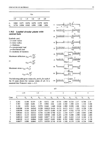
STRENGTHS OF MATERIALS                                                            55


               1.0   1.2   1.4   1.6   1.8   2.0

          k,   0.061  0.071  0.076  0.078  0.079  0.079
          k,   0.754  0.894  0.962  0.991  1.000  1.004


          I. 10.3   Loaded circular plates with
          central hole

          Symbols used:
          a = outer radius
           b = inner radius
           t = thickness
          P = concentrated load
          p = distributed load
          E = modulus of  elasticity
                                 Pa2
          Maximum deflection y,,  = k, -
                                 Et3
          or                     Pa4                  (7)
                          Ympx=kl-
                                 Et3
                              P
          Maximum stress om,=  k  -
                              t2
          or                  Pa2
                       ~,,,=k  -
                              t2
          The following table gives values of k, and k, for each of
          the  10 cases shown for  various  values  of  alb. It  is
          assumed that Poisson’s ratio v=0.3.


                       1.25          1.5           2           3           4           5

          Case   kl      k2    kl      k2    kl    k2    kl    k2    kl     k2    kl    k2
           1     0.341   0.100   0.519   1.26   0.672   1.48   0.734  1.880  0.724  2.17   0.704  2.34
          2      0.202   0.660  0.491   1.19   0.902  2.04   1.220  3.340   1.300  4.30   1.310  5.100
          3      0.184   0.592  0.414   0.976  0.664  1.440  0.824   1.880  0.830  2.08   0.8 13  2.190
          4      0.00504   0.194  0.0242   0.320  0.0810  0.454  0.172  0.673  0.217   1.021  0.238   1.305
          5      0.00199   0.105  0.0139   0.259  0.0575  0.480   0.130  0.657  0.162  0.710  0.175  0.730
          6      0.00343   0.122  0.03 13   0.336  0.1250  0.740  0.221  1.210  0.417   1.450  0.492   1.590
          7      0.0023 1   0.135  0.0183   0.410  0.0938  1.040  0.293  2.150  0.448   2.990   0.564  3.690
          8      0.00510   0.227  0.0249   0.428  0.0877  0.753  0.209   1.205  0.293   1.514  0.350   1.745
          9      0.00129   0.115  0.0064  0.220  0.0237  0.405  0.062  0.703  0.092   0.933   0.114   1.130
          10     0.00077   0.090  0.0062   0.273   0.0329  0.710  0.1 10  1.540  0.179  2.230   0.234  2.800