
Page 146 - Mechanical Engineers' Handbook (Volume 2)
P. 146
2 Thermocouples 135
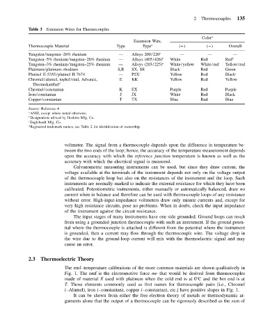
Table 3 Extension Wires for Thermocouples
Color a
Extension Wire,
Thermocouple Material Type Type a ( ) ( ) Overall
Tungsten/tungsten–26% rhenium — Alloys 200/226 b — — —
Tungsten–5% rhenium/tungsten–26% rhenium — Alloys (405/426) b White Red Red b
Tungsten–3% rhenium/tungsten–25% rhenium — Alloys (203/225) b White/yellow White/red Yellow/red
Platinum/platinum–rhodium S,R SX, SR Black Red Green
Platinel II-5355/platinel II-7674 — P2X c Yellow Red Black c
Chromel/alumel, tophel/nial, Advance, E KK Yellow Red Yellow
Thermokanthal d
Chromel/constantan K EX Purple Red Purple
Iron/constantan J JX White Red Black
Copper/constantan T TX Blue Red Blue
Source: Reference 4
a ANSI, except where noted otherwise.
b
Designations affixed by Hoskins Mfg. Co.
c Englehardt Mfg. Co.
d
Registered trademark names, see Table 2 for identification of ownership.
voltmeter. The signal from a thermocouple depends upon the difference in temperature be-
tween the two ends of the loop; hence, the accuracy of the temperature measurement depends
upon the accuracy with which the reference junction temperature is known as well as the
accuracy with which the electrical signal is measured.
Galvanometric measuring instruments can be used, but since they draw current, the
voltage available at the terminals of the instrument depends not only on the voltage output
of the thermocouple loop but also on the resistances of the instrument and the loop. Such
instruments are normally marked to indicate the external resistance for which they have been
calibrated. Potentiometric instruments, either manually or automatically balanced, draw no
current when in balance and therefore can be used with thermocouple loops of any resistance
without error. High-input-impedance voltmeters draw only minute currents and, except for
very high resistance circuits, pose no problems. When in doubt, check the input impedance
of the instrument against the circuit resistance.
The input stages of many instruments have one side grounded. Ground loops can result
from using a grounded-junction thermocouple with such an instrument. If the ground poten-
tial where the thermocouple is attached is different from the potential where the instrument
is grounded, then a current may flow through the thermocouple wire. The voltage drop in
the wire due to the ground-loop current will mix with the thermoelectric signal and may
cause an error.
2.3 Thermoelectric Theory
The emf–temperature calibrations of the more common materials are shown qualitatively in
Fig. 1. The emf is the electromotive force mv that would be derived from thermocouples
made of material X used with platinum when the cold end is at 0 C and the hot end is at
T. Those elements commonly used as first names for thermocouple pairs [i.e., Chromel
(–Alumel), iron (–constantan), copper (–constantan), etc.] have positive slopes in Fig. 1.
It can be shown from either the free-electron theory of metals or thermodynamic ar-
guments alone that the output of a thermocouple can be rigorously described as the sum of