
Page 148 - Mechanical Engineers' Handbook (Volume 2)
P. 148
2 Thermocouples 137
2.4 Graphical Analysis of Circuits
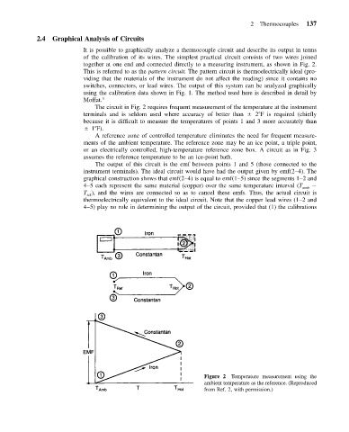
It is possible to graphically analyze a thermocouple circuit and describe its output in terms
of the calibration of its wires. The simplest practical circuit consists of two wires joined
together at one end and connected directly to a measuring instrument, as shown in Fig. 2.
This is referred to as the pattern circuit. The pattern circuit is thermoelectrically ideal (pro-
viding that the materials of the instrument do not affect the reading) since it contains no
switches, connectors, or lead wires. The output of this system can be analyzed graphically
using the calibration data shown in Fig. 1. The method used here is described in detail by
Moffat. 3
The circuit in Fig. 2 requires frequent measurement of the temperature at the instrument
terminals and is seldom used where accuracy of better than 2 F is required (chiefly
because it is difficult to measure the temperatures of points 1 and 3 more accurately than
1 F).
A reference zone of controlled temperature eliminates the need for frequent measure-
ments of the ambient temperature. The reference zone may be an ice point, a triple point,
or an electrically controlled, high-temperature reference zone box. A circuit as in Fig. 3
assumes the reference temperature to be an ice-point bath.
The output of this circuit is the emf between points 1 and 5 (those connected to the
instrument terminals). The ideal circuit would have had the output given by emf(2–4). The
graphical construction shows that emf(2–4) is equal to emf(1–5) since the segments 1–2 and
4–5 each represent the same material (copper) over the same temperature interval (T amb
T ), and the wires are connected so as to cancel these emfs. Thus, the actual circuit is
ref
thermoelectrically equivalent to the ideal circuit. Note that the copper lead wires (1–2 and
4–5) play no role in determining the output of the circuit, provided that (1) the calibrations
Figure 2 Temperature measurement using the
ambient temperature as the reference. (Reproduced
from Ref. 2, with permission.)