
Page 153 - Mechanical Engineers' Handbook (Volume 2)
P. 153
142 Temperature and Flow Transducers
2.7 Switches, Connectors, Zone Boxes, and Reference Baths
A thermocouple switch or connector must not produce emf that would contaminate the
temperature signal. By their very nature, switches and connectors connect several materials
together and are susceptible to generation of thermoelectric emf.
The principal defense against spurious emf is to ensure that the switch or connector is
isothermal, not only on the whole but in detail. The mechanical energy dissipated as heat
when the switch is moved appears first as a high-temperature spot on the oxide films of the
two contacts. Substantial temperature gradients may persist for several milliseconds after a
switch movement.
Connectors frequently are used to join a thermocouple to lead wires, often in a location
near the test apparatus. Temperature gradients within connectors may generate spurious sig-
nals. It is important to insulate the outer shell and provide a good conduction path inside
the connector.
Switches and connectors made of thermocouple grade alloys will minimize the troubles
caused by poor thermal protection, but good thermal design is still necessary.
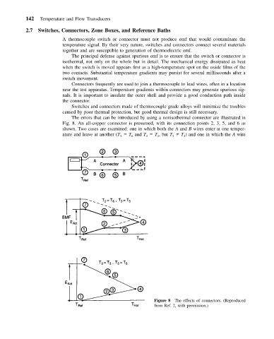
The errors that can be introduced by using a nonisothermal connector are illustrated in
Fig. 8. An all-copper connector is presumed, with its connection points 2, 3, 5, and 6 as
shown. Two cases are examined: one in which both the A and B wires enter at one temper-
ature and leave at another (T T and T T ,but T T ) and one in which the A wire
5
2
3
6
2
3
Figure 8 The effects of connectors. (Reproduced
from Ref. 2, with permission.)