
Page 154 - Mechanical Engineers' Handbook (Volume 2)
P. 154
2 Thermocouples 143
enters and leaves at one temperature while the B wire enters and leaves at some other
temperature (T T and T T ,but T T ). The E–T diagram shows the latter situation
6
5
5
3
2
2
causes no error regardless of the type of material in the connector, since there is never a
temperature gradient along the connector material. In the first case, the resultant signal is in
error, having ‘‘lost’’ the entire amount of the temperature interval across the connector.
Reference baths which provide stable and uniform zones for termination of thermocou-
ple systems are available. These generally consist of a heated or cooled zone box thermo-
statically controlled to remain at some specified temperature. Laboratory users may well use
an ice bath or triple-point cell. For most engineering purposes, a bath made with ice and
water sufficiently pure for human consumption will be within a few hundredths of a degree
of 0 C if certain simple precautions are followed.
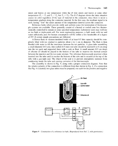
A Dewar flask or vacuum-insulated bottle of at least 0.5 liter capacity should be com-
pletely filled with ice crushed to particles about – 1 to – 1 cm in diameter. The flask is then
4 2
flooded with water to fill the interstices between the ice particles. A glass tube resembling
a small-diameter (0.5-cm), thin-walled (0.5-mm) test tube should be inserted 6 or 8 cm deep
into the ice pack and supported there with a cork or float. A small amount (0.5 cm deep)
of silicone oil should be placed in the bottom of the tube to improve the thermal contact
between the junction and the ice-water mixture. The reference thermocouple junction is then
inserted into the tube until it touches the bottom of the tube and is secured at the top of the
tube with a gas-tight seal. The object of the seal is to prevent atmospheric moisture from
condensing inside the tube and causing corrosion of the thermocouple.
The assembly is shown in Fig. 9, along with a proper connection diagram. Note that
the relative polarity of the connection is different from that shown in Fig. 4. If a connection
like Fig. 4 is desired, two glass tubes must be prepared, one each for the positive and negative
Figure 9 Construction of a reference ice bath. (Reproduced from Ref. 2, with permission.)