
Page 158 - Mechanical Engineers' Handbook (Volume 2)
P. 158
2 Thermocouples 147
heat the wire in the suspected region. A homogeneous material will not produce any emf,
as shown earlier in Fig. 5. An inhomogeneous material will have different calibrations on
the upslope and downslope sides of the temperature excursion and will produce a net emf.
This process is illustrated in Fig. 12.
The best technique for identifying a service-induced inhomogeneity is ‘‘side-by-side’’
running or comparison by replacement. Neither is very convenient, but on the other hand,
there is no alternative. It is not within the present state of the art, regardless of how much
effort is expended, to be able to interpret the readings from an inhomogeneous thermocouple
in an arbitrary environment.
2.10 Thermoelectric Materials Connected in Parallel
Thermocouple materials are usually thought of as being connected in series with respect to
the direction of the temperature gradient. There are situations, however, where two materials
are in parallel electrical contact along their length. In such cases, the thermoelectric potential
causes a distributed current to circulate in the materials. The net effect of such a configuration
can be computed if the geometries and material properties are known.
There are three applications for which this effect is known to be of importance: (1) in
the design of plated-junction thermopiles, (2) in attempts to precisely measure surface tem-
peratures using thermocouples attached with solder, and (3) in the case of distributed failure
of thermocouple insulation, usually at high temperatures.
The essential features of this parallel circuitry can be illustrated by discussion of the
thermopile design and the shunted thermocouple situation.
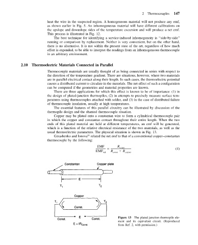
Copper may be plated onto a constantan wire to form a cylindrical thermocouple pair
in which the copper and constantan contact throughout their entire length. When the two
ends of this plated material are held at different temperatures, an emf will be generated,
which is a function of the relative electrical resistance of the two materials, as well as the
usual thermoelectric parameters. The physical situation is shown in Fig. 13.
11
Gerashenko and Ionova related the net emf to that of a conventional copper–constantan
thermocouple by the following:
EMF R const
(4)
R
EMF std R const copper
Figure 13 The plated junction thermopile ele-
ment and its equivalent circuit. (Reproduced
from Ref. 2, with permission.)