
Page 159 - Mechanical Engineers' Handbook (Volume 2)
P. 159
148 Temperature and Flow Transducers
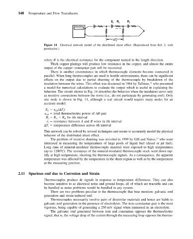
Figure 14 Electrical network model of the distributed shunt effect. (Reproduced from Ref. 2, with
permission.)
where R is the electrical resistance for the component named in the length direction.
Thick copper platings will produce low resistance in the copper, and almost the entire
output of the copper–constantan pair will be recovered.
There is another circumstance in which thermocouple elements become connected in
parallel. When long thermocouples are used in hostile environments, there can be significant
effects on the output due to partial shunting of the thermocouple by breakdown of the
12
insulation between the wires. This effect was discussed in 1964 by Tallman, who presented
a model for numerical calculations to evaluate the output which is useful in explaining the
behavior. The circuit shown in Fig. 14 describes the behavior when the insulators serve only
as resistive connections between the wires (i.e., do not participate by generating emf). Only
one node is shown in Fig. 14, although a real circuit would require many nodes for an
accurate model:
E ( T )
AB
i
1
AB total thermoelectric power of AB pair
R R R for ith interval
B
i
A
r resistance between A and B wires in ith interval
i
T temperature difference across ith interval
i
This network can be solved by several techniques and seems to accurately model the physical
behavior of the distributed shunt effect.
The problem of resistive shunting was revisited in 1999 by Gill and Nakos, who were
13
interested in measuring the temperatures of large pools of liquid fuel (diesel or jet fuel).
Long runs of mineral-insulated thermocouple material were exposed to high temperatures
(up to 1200 C). The resistance of the mineral-insulated thermocouple stock went down rap-
idly at high temperature, shunting the thermocouple signals. As a consequence, the apparent
temperature was affected by the temperature in the shunt region as well as by the temperature
at the measuring junction.
2.11 Spurious emf due to Corrosion and Strain
Thermocouples produce dc signals in response to temperature differences. They can also
become sensitive to ac electrical noise and ground loops, all of which are tractable and can
be handled as noise problems would be handled in any system.
There are two problems peculiar to the thermocouple that bear mention: galvanic emf
generation and strain-induced emf.
Thermocouples necessarily involve pairs of dissimilar materials and hence are liable to
galvanic emf generation in the presence of electrolytes. The iron–constantan pair is the most
vigorous, being capable of generating a 250-mV signal when immersed in an electrolyte.
The galvanic emf generated between iron and constantan opposes the thermoelectric
signal; that is, the voltage drop of the current through the measuring loop opposes the thermo-