
Page 164 - Mechanical Engineers' Handbook (Volume 2)
P. 164
3 Resistance Temperature Detectors 153
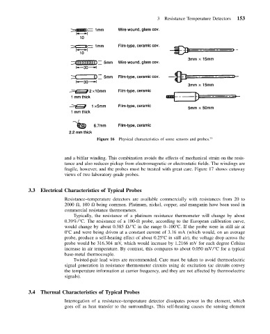
Figure 16 Physical characteristics of some sensors and probes. 33
and a bifilar winding. This combination avoids the effects of mechanical strain on the resis-
tance and also reduces pickup from electromagnetic or electrostatic fields. The windings are
fragile, however, and the probes must be treated with great care. Figure 17 shows cutaway
views of two laboratory-grade probes.
3.3 Electrical Characteristics of Typical Probes
Resistance–temperature detectors are available commercially with resistances from 20 to
2000 , 100 being common. Platinum, nickel, copper, and manganin have been used in
commercial resistance thermometers.
Typically, the resistance of a platinum resistance thermometer will change by about
0.39%/ C. The resistance of a 100- probe, according to the European calibration curve,
would change by about 0.385 / C in the range 0–100 C. If the probe were in still air at
0 C and were being driven at a constant current of 3.16 mA (which would, on an average
probe, produce a self-heating effect of about 0.25 C in still air), the voltage drop across the
probe would be 316.304 mV, which would increase by 1.2166 mV for each degree Celsius
increase in air temperature. By contrast, this compares to about 0.050 mV/ C for a typical
base-metal thermocouple.
Twisted-pair lead wires are recommended. Care must be taken to avoid thermoelectric
signal generation in resistance thermometer circuits using dc excitation (ac circuits convey
the temperature information at carrier frequency, and they are not affected by thermoelectric
signals).
3.4 Thermal Characteristics of Typical Probes
Interrogation of a resistance–temperature detector dissipates power in the element, which
goes off as heat transfer to the surroundings. This self-heating causes the sensing element