
Page 166 - Mechanical Engineers' Handbook (Volume 2)
P. 166
3 Resistance Temperature Detectors 155
of the pulse and the thermal capacitance of the sensor rather than on the resistances between
the sensor and the specimen.
Resistance–temperature detectors (RTDs) are subject to all of the installation errors and
environmental errors of any immersion sensor and, because of the detectors’ larger size, are
usually affected more than thermocouples or thermistors. Since RTDs are usually selected
by investigators who wish to claim high accuracy for their data, the higher susceptibility to
environmental error may be a significant disadvantage.
The internal structure of most RTDs is sufficiently complex that their thermal response
is not first order. As a consequence, it is very difficult to interpret transients. The term time
constant, which applies only to first-order systems, should not be applied to RTDs in general.
If a time constant is quoted for a RTD, it may only mean ‘‘the time required for 63.2%
completion of the response to a step change,’’ and it may not imply the other important
consequences of first-order response. Quoted values, from one probe supplier, of ‘‘time to
90% completion’’ range from 9 to 140 s for probes of 1.0–4.5 mm in diameter exposed to
air at 1 m/s.
3.5 Measuring Circuits
Resistance–temperature detectors require a source of power and a means of measuring re-
sistance or voltage.
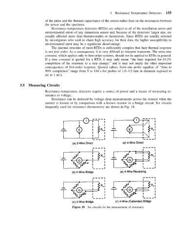
Resistance can be deduced by voltage drop measurements across the resistor when the
current is known or by comparison with a known resistor in a bridge circuit. Six circuits
frequently used for resistance thermometry are shown in Fig. 18.
Figure 18 Six circuits for the measurement of resistance.