
Page 179 - Mechanical Engineers' Handbook (Volume 2)
P. 179
168 Temperature and Flow Transducers
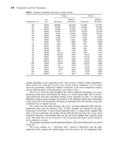
Table 9 Resistance and Relative Resistance of Typical Probes
Probe 1 Probe 2
1/T Relative Relative
Temperature ( C) (K) Resistance Resistance Resistance Resistance
80 .00518 1660000 225.6968 2211000 225.7044
70 .00493 702300 95.4861 935600 95.5084
60 .00469 316500 43.0320 421500 43.0278
50 .00448 151050 20.5370 201100 20.5288
40 .00429 75790 10.3046 101000 10.3103
30 .00412 39860 5.4194 53100 5.4206
20 .00395 21870 2.9735 29130 2.9737
10 .00380 12460 1.6941 16600 1.6946
0 .00366 7355 1.0000 9796 1.0000
10 .00353 4482 .6094 5971 .6095
20 .00341 2814 .3826 3748 .3826
30 .00330 1815 .2468 2417 .2467
40 .00319 1200 .1632 1598 .1631
50 .00310 811.30 .1103 1081 .1104
60 .00300 560.30 .0762 746.30 .0762
70 .00292 394.50 .0536 525.40 .0536
80 .00283 282.70 .0384 376.90 .0385
90 .00275 206.10 .0280 274.90 .0281
100 .00268 152.80 .0208 203.80 .0208
110 .00261 115 .0156 153.20 .0156
120 .00254 87.70 .0119 116.80 .0119
130 .00248 67.80 .0092 90.20 .0092
140 .00242 53 .0072 70.40 .0072
150 .00236 41.90 .0057 55.60 .0057
reading depending on the temperature level. The accuracy is better at high temperatures.
These devices are vulnerable to errors from several sources: calibration, size of source,
emissivity uncertainty, background radiation (especially in the lower temperature ranges),
and gas path absorption of the infrared by water vapor or CO .
2
One way to avoid gas path absorption and source emissivity uncertainty is to use a
blackbody cavity source and transmit the energy via a closed optical path. This is the prin-
ciple behind the fiber-optic blackbody-sensing system described by Dils. 49 A fiber-optic
blackbody radiation sensor measures the intensity of the radiation emitted from a blackbody
cavity at the end of an optical fiber and deduces temperature from the intensity, using well-
established laws of radiant emission.
The system has four main elements: the cavity, the high-temperature fiber, the low-
temperature fiber, and the processor. Two of these elements are exposed to the high-
temperature environment. A typical high-temperature fiber is a single-crystal sapphire fiber
about 1.25 mm in diameter and usually between 100 and 250 mm long. The cavity can be
formed by sputtering a thin metallic film onto the end of the sapphire fiber, typically about
5 m. The metal layer can be covered by a film of alumina (also about 5 m) to protect it
from oxidation or erosion.
The general arrangement and the principal features of the data interpretation are shown
in Fig. 25.
The cavity radiates as a ‘‘dark-gray body’’ (almost a blackbody) and the high-
temperature fiber conducts the radiant energy from the cavity to the low-temperature fiber,