
Page 209 - Mechanical Engineers' Handbook (Volume 2)
P. 209
198 Signal Processing
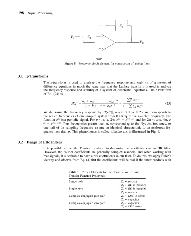
Figure 8 Prototype circuit element for construction of analog filter.
3.1 z-Transforms
The z-transform is used to analyze the frequency response and stability of a system of
difference equations in much the same way that the Laplace transform is used to analyze
the frequency response and stability of a system of differential equations. The z-transform
of Eq. (24) is
M j
a az 1 az M 0 az
j
H(z) 0 1 M (25)
1 bz 1 bz N 1 j 1 bz j
N
N
1
j
j
We determine the frequency response by
H(e )
, where 0 2 and corresponds to
the scaled frequencies of our sampled system from 0 Hz up to the sampled frequency. The
function e j is a periodic signal. For 2 , e j e j( ) , and for 2 4 , e
j e j( 2 ) . Thus frequencies greater than , corresponding to the Nyquist frequency, or
one-half of the sampling frequency assume an identical characteristic to an analogous fre-
quency less than . This phenomenon is called aliasing and is illustrated in Fig. 9.
3.2 Design of FIR Filters
It is possible to use the Fourier transform to determine the coefficients to an FIR filter.
However, the Fourier coefficients are generally complex numbers, and when working with
real signals, it is desirable to have a real coefficients in our filter. To do this, we apply Euler’s
identity and observe from Eq. (4) that the coefficients will be real if the inner products with
Table 1 Circuit Elements for the Construction of Basic
Transfer Function Prototypes
Single pole Z 1 ← resistor
Z 2 ← RC in parallel
Single zero Z 1 ← RC in parallel
Z 2 ← resistor
Complex-conjugate pole pair Z 1 ← LRC in series
Z 2 ← capacitor
Complex-conjugate zero pair Z 1 ← capacitor
Z 2 ← LRC series