
Page 210 - Mechanical Engineers' Handbook (Volume 2)
P. 210
3 Basic Digital Filter 199
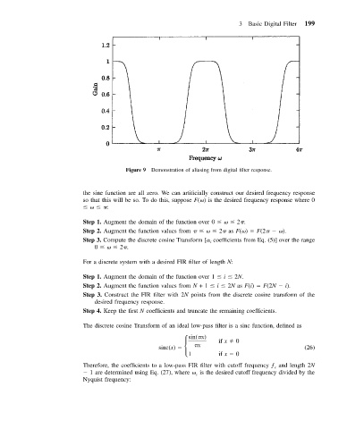
Figure 9 Demonstration of aliasing from digital filter response.
the sine function are all zero. We can artificially construct our desired frequency response
so that this will be so. To do this, suppose F( ) is the desired frequency response where 0
:
Step 1. Augment the domain of the function over 0 2 .
Step 2. Augment the function values from 2 as F( ) F(2 ).
Step 3. Compute the discrete cosine Transform [ coefficients from Eq. (5)] over the range
i
0 2 .
For a discrete system with a desired FIR filter of length N:
Step 1. Augment the domain of the function over 1 i 2N.
Step 2. Augment the function values from N +1 i 2N as F(i) F(2N i).
Step 3. Construct the FIR filter with 2N points from the discrete cosine transform of the
desired frequency response.
Step 4. Keep the first N coefficients and truncate the remaining coefficients.
The discrete cosine Transform of an ideal low-pass filter is a sinc function, defined as
sin( x) if x 0
sinc(x) x (26)
1 if x 0
Therefore, the coefficients to a low-pass FIR filter with cutoff frequency ƒ and length 2N
c
1 are determined using Eq. (27), where is the desired cutoff frequency divided by the
c
Nyquist frequency: