
Page 667 - Mechanical Engineers' Handbook (Volume 2)
P. 667
658 Controller Design
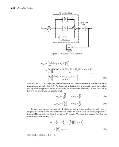
Figure 35 Generalized PID controller.
G Ks K
K
i
d
pid
s 1 p s
d
[K /K (K /K ) ]s [K /K ]s 1
2
d
i
p
i
d
p
i
d
K i
s s 1
d
s / 2 pid (2 / )s 1
2
pid
pid
K i
s s 1 (33)
d
Note that Eq. (33) is simply the transfer function of a lead compensator combined with an
integrator, as given by Eq. (19). As discussed in Section 3.1, it is usually possible to place
the lag break frequency a factor of 10 above the lead natural frequency. In this case, the d
terms in the numerator are usually small:
K K
pid K i for d (34)
d
d K p
2 K p
K
p
pid pid for (35)
d
K d K i
In some applications, second-order lead compensation is not required. In such cases, a
simplified version of the PID controller can often be useful. This so-called proportional-
integral (PI) controller is formed by setting K to zero. The resulting transfer function can
d
then be derived from Eq. (33):
G K K i K p s 1
K i
p
pi
s s K i
K
i
pi
s ( s 1) (36)
This result is similar to Eq. (18).