Page 664 - Mechanical Engineers' Handbook (Volume 2)
P. 664

5 Prefilters and Feedforward  655

                                                U 7    [H   (GG )]   G G 3
                                                                      2
                                                                1
                                                U c    2    2  3  1   GGH  2
                                                                       2
                                                                         3
                                                     GGH   1      GG
                                                      2  3  2      2  3    1.0                  (27)
                                                       GG  3   1   GGH  2
                                                         2
                                                                      3
                                                                    2
                              Of course, it is not possible to actually achieve the ideal result given by Eq. (27) because
                           of the lags associated with the lead network in the feedforward path. To illustrate the practical
                           aspects of feedforward, it is useful to reexamine the example of Fig. 28. If the forward-loop
                           integrator is electronic in nature, the use of feedforward offers some advantages over the
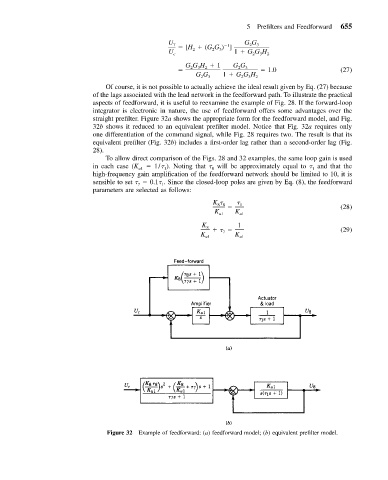
                           straight prefilter. Figure 32a shows the appropriate form for the feedforward model, and Fig.
                           32b shows it reduced to an equivalent prefilter model. Notice that Fig. 32a requires only
                           one differentiation of the command signal, while Fig. 28 requires two. The result is that its
                           equivalent prefilter (Fig. 32b) includes a first-order lag rather than a second-order lag (Fig.
                           28).
                              To allow direct comparison of the Figs. 28 and 32 examples, the same loop gain is used
                           in each case (K    1/  ). Noting that   will be approximately equal to   and that the
                                       u1      1            8                           1
                           high-frequency gain amplification of the feedforward network should be limited to 10, it is
                           sensible to set     0.1  . Since the closed-loop poles are given by Eq. (8), the feedforward
                                       7      1
                           parameters are selected as follows:
                                                            K         1                         (28)
                                                             88
                                                             K    K
                                                              u1    u1
                                                         K         1
                                                          8                                     (29)
                                                         K u1  7  K u1


                               Figure 32 Example of feedforward: (a) feedforward model; (b) equivalent prefilter model.
   659   660   661   662   663   664   665   666   667   668   669