
Page 661 - Mechanical Engineers' Handbook (Volume 2)
P. 661
652 Controller Design
function that is the inverse of the desired U/U transfer function. This can be seen with the
c
aid of Fig. 27 by eliminating the prefilter. If the forward-loop gain is high enough, U/U
c
1/H . This technique is further discussed in Section 4.1, and an example is given in Fig. 22.
1
5.2 Lead Prefilters
Since the closed-loop response characteristics of most servoloops are dominated by lag el-
ements, lead prefilters are often used to improve the response to command inputs. Theoret-
ically, this can be accomplished by simply making the prefilter transfer function equal to the
reciprocal of the servoloop closed-loop transfer function. For the generalized system illus-
trated in Fig. 27, the ideal prefilter would be
1 GH
G 1 1 (25)
pf
G 1
Unfortunately, the lead required to accomplish this will be limited by its associated poles,
which must be selected to prevent excessive electrical noise (as discussed in Section 3.1).
Also lead prefilters can accentuate the oscillatory tendencies of a poorly damped servoloop.
Even for a well-damped servoloop, overshooting response can occur if the servoloop param-
eters vary substantially over the operating envelope. In many cases, the lead network may
be more effective if it is moved to the forward loop so that higher servoloop gains can be
used.
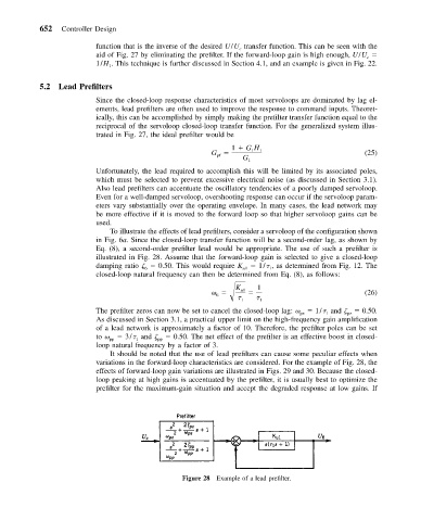
To illustrate the effects of lead prefilters, consider a servoloop of the configuration shown
in Fig. 6a. Since the closed-loop transfer function will be a second-order lag, as shown by
Eq. (8), a second-order prefilter lead would be appropriate. The use of such a prefilter is
illustrated in Fig. 28. Assume that the forward-loop gain is selected to give a closed-loop
damping ratio 0.50. This would require K u1 1/ , as determined from Fig. 12. The
6
1
closed-loop natural frequency can then be determined from Eq. (8), as follows:
K 1
u1 (26)
6
1 1
The prefilter zeros can now be set to cancel the closed-loop lag: 1/ and 0.50.
pz
1
pz
As discussed in Section 3.1, a practical upper limit on the high-frequency gain amplification
of a lead network is approximately a factor of 10. Therefore, the prefilter poles can be set
to pp 3/ and pp 0.50. The net effect of the prefilter is an effective boost in closed-
1
loop natural frequency by a factor of 3.
It should be noted that the use of lead prefilters can cause some peculiar effects when
variations in the forward-loop characteristics are considered. For the example of Fig. 28, the
effects of forward-loop gain variations are illustrated in Figs. 29 and 30. Because the closed-
loop peaking at high gains is accentuated by the prefilter, it is usually best to optimize the
prefilter for the maximum-gain situation and accept the degraded response at low gains. If
Figure 28 Example of a lead prefilter.