
Page 685 - Mechanical Engineers' Handbook (Volume 2)
P. 685
676 Controller Design
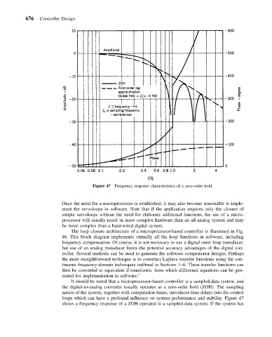
Figure 47 Frequency response characteristics of a zero-order hold.
Once the need for a microprocessor is established, it may also become reasonable to imple-
ment the servoloops in software. Note that if the application requires only the closure of
simple servoloops without the need for elaborate additional functions, the use of a micro-
processor will usually result in more complex hardware than an all-analog system and may
be more complex than a hard-wired digital system.
The loop closure architecture of a microprocessor-based controller is illustrated in Fig.
46. This block diagram implements virtually all the loop functions in software, including
frequency compensation. Of course, it is not necessary to use a digital outer loop transducer,
but use of an analog transducer limits the potential accuracy advantages of the digital con-
troller. Several methods can be used to generate the software compensator designs. Perhaps
the most straightforward technique is to construct Laplace transfer functions using the con-
tinuous frequency-domain techniques outlined in Sections 1–6. These transfer functions can
then be converted to equivalent Z-transforms, from which difference equations can be gen-
erated for implementation in software. 7
It should be noted that a microprocessor-based controller is a sampled-data system, and
the digital-to-analog converter usually operates as a zero-order hold (ZOH). The sampling
nature of the system, together with computation times, introduces time delays into the control
loops which can have a profound influence on system performance and stability. Figure 47
shows a frequency response of a ZOH operated in a sampled-data system. If the system has