
Page 696 - Mechanical Engineers' Handbook (Volume 2)
P. 696
2 Programmable Controllers (PLCs) 687
2 PROGRAMMABLE CONTROLLERS (PLCs)
2.1 Principles of Operation
PLC is defined by the IEC as
A digitally operating electronic system, designed for use in an industrial environment, which uses
a programmable memory for the internal storage of user-oriented instructions for implementing
specific functions such as logic, sequencing, timing, counting, and arithmetic, to control, through
digital or analog inputs and outputs, various types of machines or processes. Both the PLC and
its associated peripherals are designed to be easily integrable into an industrial control system
and easily used in all their intended functions. 7
The hardware architecture of almost all programmable controllers is the same as that for the
GPCD shown in Fig. 3.
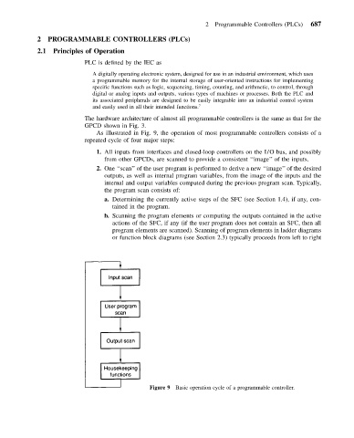
As illustrated in Fig. 9, the operation of most programmable controllers consists of a
repeated cycle of four major steps:
1. All inputs from interfaces and closed-loop controllers on the I/O bus, and possibly
from other GPCDs, are scanned to provide a consistent ‘‘image’’ of the inputs.
2. One ‘‘scan’’ of the user program is performed to derive a new ‘‘image’’ of the desired
outputs, as well as internal program variables, from the image of the inputs and the
internal and output variables computed during the previous program scan. Typically,
the program scan consists of:
a. Determining the currently active steps of the SFC (see Section 1.4), if any, con-
tained in the program.
b. Scanning the program elements or computing the outputs contained in the active
actions of the SFC, if any (if the user program does not contain an SFC, then all
program elements are scanned). Scanning of program elements in ladder diagrams
or function block diagrams (see Section 2.3) typically proceeds from left to right
Figure 9 Basic operation cycle of a programmable controller.