
Page 82 - Mechanical Engineers' Handbook (Volume 2)
P. 82
2 Flexural Devices in Measurement Systems 71
tube is typically used to modify the alternating current (ac) impedance of bridge transducers.
Bourdon tubes can be integrated into transducers to achieve extremely high accuracies and
have been manufactured from perfectly elastic materials such as quartz.
Transducers employing Bourdon tubes tend to be physically large and easily damaged
by environmental inputs such as acceleration. In addition, the tubes themselves afford poor
frequency response to time-varying pressure.
2.3 Clamped Diaphragms
Clamped diaphragms are another flexure used to transform a measurand into a strain or
displacement proportional to applied pressure. A small, flat, circular diaphragm can be made
simply, and it can be placed flush against surfaces whose flow dynamics are being studied.
This type of diaphragm is typically designed to deflect in accord with theory associated with
clamped circular plates. Corrugated diaphragms provide extensibility over a greater linear
operating range than do flat diaphragms. A catenary diaphragm consists of a flexurally weak
seal diaphragm bearing against a thin cylinder whose motion is measured. The compliance
of a flat, clamped circular diaphragm is defined as
2
4
y 3R (1 )
0
(2)
3
P 16tE
where y is the deflection of the center of the diaphragm, P is the applied pressure, R is the
0
diaphragm radius, is Poisson’s ratio, t is the diaphragm thickness, and E is the modulus
of elasticity of the diaphragm material. Somewhat analogous to the cantilever beam, a com-
pliant diaphragm will have a large radius, be thin, and be made of a low-modulus material.
Equation (2) holds for deflections no greater than t.
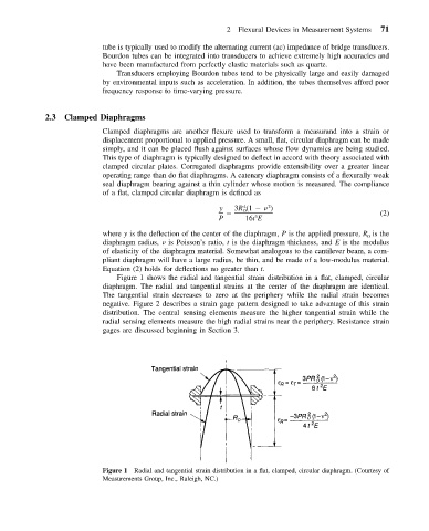
Figure 1 shows the radial and tangential strain distribution in a flat, clamped, circular
diaphragm. The radial and tangential strains at the center of the diaphragm are identical.
The tangential strain decreases to zero at the periphery while the radial strain becomes
negative. Figure 2 describes a strain gage pattern designed to take advantage of this strain
distribution. The central sensing elements measure the higher tangential strain while the
radial sensing elements measure the high radial strains near the periphery. Resistance strain
gages are discussed beginning in Section 3.
Figure 1 Radial and tangential strain distribution in a flat, clamped, circular diaphragm. (Courtesy of
Measurements Group, Inc., Raleigh, NC.)