Page 331 - Mechanical Engineers' Handbook (Volume 4)
P. 331

320   Heat Exchangers, Vaporizers, Condensers

           4.2 Vibration
                          A problem with shell and tube heat exchangers that is becoming more frequent as heat
                          exchangers tend to become larger and design velocities tend to become higher is tube failure
                          due to flow-induced tube vibration. Summaries including recommended methods of analysis
                                            51
                                                           3
                          are given by Chenoweth and by Mueller. In general, tube vibration problems tend to occur
                          when the distance between baffles or tube-support plates is too great. Maximum baffle spac-
                          ings recommended by TEMA were based on the maximum unsupported length of tube that
                          will not sag significantly. Experience has shown that flow-induced vibration can still occur
                          at TEMA maximum baffle spacing, but for less than about 0.7 times this spacing most
                          vibration can be eliminated at normal design velocities (see Section 2.4). Taborek 11  gives
                          the following equations for TEMA maximum unsupported tube lengths (L ), inches.
                                                                                    su
                             Steel and Steel Alloy Tubes
                                                             3
                                                     For D   ⁄4–2 in.,                        (59)
                                                          o
                                                        L   52D   21
                                                                 o
                                                         su
                                                              1
                                                                3
                                                      For D   ⁄4–⁄4 in.,                      (60)
                                                          o
                                                         L   68D   9
                                                          su
                                                                 o
                             Aluminum and Copper Alloy Tubes
                                                             3
                                                     For D   ⁄4–2 in.,                        (61)
                                                          o
                                                        L   46D   17
                                                                 o
                                                         su
                                                      For D   ⁄4–⁄4 in.,                      (62)
                                                              1
                                                                3
                                                          o
                                                         L   60D   7
                                                          su
                                                                 o
                          For segmental baffles with tubes in the windows, Fig. 9, the maximum baffle spacing is one-
                          half the maximum unsupported tube length.
                             For very large bundle diameters, segmental or even double segmental baffles may not
                          be suitable, since the spacing required to prevent vibration may produce too high pressure
                          drops. (In addition, flow distribution considerations require that the ratio of baffle spacing
                          to shell diameter not be less than about 0.2.) In such cases, one commonly used solution is
                          to eliminate tubes in the baffle windows so that intermediate support plates can be used and
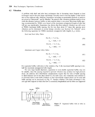
                          baffle spacing can be increased; see Fig. 17. Another solution, with many advantages is the
                          rod-type tube support in which the flow is essentially longitudinal and the tubes are supported


                                                               Figure 17 Segmental baffles with no tubes in
                                                               window.
   326   327   328   329   330   331   332   333   334   335   336