
Page 328 - Mechanical Engineers' Handbook (Volume 4)
P. 328
3 Rating Methods 317
Heat-Transfer Coefficients
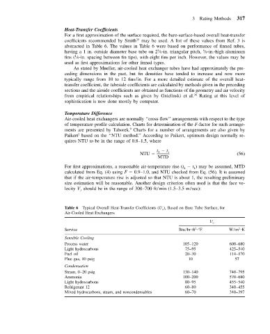
For a first approximation of the surface required, the bare-surface-based overall heat-transfer
coefficients recommended by Smith 35 may be used. A list of these values from Ref. 3 is
abstracted in Table 6. The values in Table 6 were based on performance of finned tubes,
5
3
having a 1 in. outside diameter base tube on 2 ⁄8-in. triangular pitch, ⁄8-in.-high aluminum
1
fins ( ⁄8-in. spacing between fin tips), with eight fins per inch. However, the values may be
used as first approximations for other finned types.
As stated by Mueller, air-cooled heat exchanger tubes have had approximately the pre-
ceding dimensions in the past, but fin densities have tended to increase and now more
typically range from 10 to 12 fins/in. For a more detailed estimate of the overall heat-
transfer coefficient, the tubeside coefficients are calculated by methods given in the preceding
sections and the airside coefficients are obtained as functions of fin geometry and air velocity
from empirical relationships such as given by Gnielinski et al. 36 Rating at this level of
sophistication is now done mostly by computer.
Temperature Difference
Air-cooled heat exchangers are normally ‘‘cross-flow’’ arrangements with respect to the type
of temperature profile calculation. Charts for determination of the F-factor for such arrange-
9
ments are presented by Taborek. Charts for a number of arrangements are also given by
2
Paikert based on the ‘‘NTU method.’’ According to Paikert, optimum design normally re-
quires NTU to be in the range of 0.8–1.5, where
t t
NTU 2 1 (56)
MTD
For first approximations, a reasonable air-temperature rise (t t ) may be assumed, MTD
1
2
calculated from Eq. (4) using F 0.9–1.0, and NTU checked from Eq. (56). It is assumed
that if the air-temperature rise is adjusted so that NTU is about 1, the resulting preliminary
size estimation will be reasonable. Another design criterion often used is that the face ve-
locity V should be in the range of 300–700 ft/min (1.5–3.5 m/sec):
ƒ
Table 6 Typical Overall Heat-Transfer Coefficients (U o ), Based on Bare Tube Surface, for
Air-Cooled Heat Exchangers
U o
2
2
Service Btu/hr ft F W/m K
Sensible Cooling
Process water 105–120 600–680
Light hydrocarbons 75–95 425–540
Fuel oil 20–30 114–170
Flue gas, 10 psig 10 57
Condensation
Steam, 0–20 psig 130–140 740–795
Ammonia 100–200 570–680
Light hydrocarbons 80–95 455–540
Refrigerant 12 60–80 340–455
Mixed hydrocarbons, steam, and noncondensables 60–70 340–397