
Page 384 - Mechanical Engineers' Handbook (Volume 4)
P. 384
1 Thermal Modeling 373
substrate or heat spreader (required to be 3 to 5 times thicker than the square root of the
heat source area) can be expressed as 1
0.475 0.62 0.13 2
R (K/W) (6)
sp
k A c
where is the ratio of the heat source area to the substrate area, k is the thermal conductivity
of the substrate, and A is the area of the heat source.
c
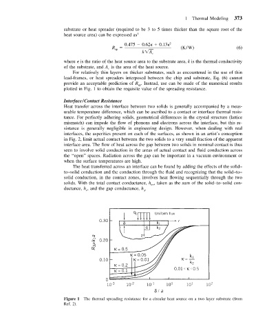
For relatively thin layers on thicker substrates, such as encountered in the use of thin
lead-frames, or heat spreaders interposed between the chip and substrate, Eq. (6) cannot
provide an acceptable prediction of R . Instead, use can be made of the numerical results
sp
plotted in Fig. 1 to obtain the requisite value of the spreading resistance.
Interface/Contact Resistance
Heat transfer across the interface between two solids is generally accompanied by a meas-
urable temperature difference, which can be ascribed to a contact or interface thermal resis-
tance. For perfectly adhering solids, geometrical differences in the crystal structure (lattice
mismatch) can impede the flow of phonons and electrons across the interface, but this re-
sistance is generally negligible in engineering design. However, when dealing with real
interfaces, the asperities present on each of the surfaces, as shown in an artist’s conception
in Fig. 2, limit actual contact between the two solids to a very small fraction of the apparent
interface area. The flow of heat across the gap between two solids in nominal contact is thus
seen to involve solid conduction in the areas of actual contact and fluid conduction across
the ‘‘open’’ spaces. Radiation across the gap can be important in a vacuum environment or
when the surface temperatures are high.
The heat transferred across an interface can be found by adding the effects of the solid–
to–solid conduction and the conduction through the fluid and recognizing that the solid–to–
solid conduction, in the contact zones, involves heat flowing sequentially through the two
solids. With the total contact conductance, h , taken as the sum of the solid–to–solid con-
co
ductance, h , and the gap conductance, h g
c
Figure 1 The thermal spreading resistance for a circular heat source on a two layer substrate (from
Ref. 2).