
Page 380 - Mechanical Engineers' Handbook (Volume 4)
P. 380
4 Benefits 369
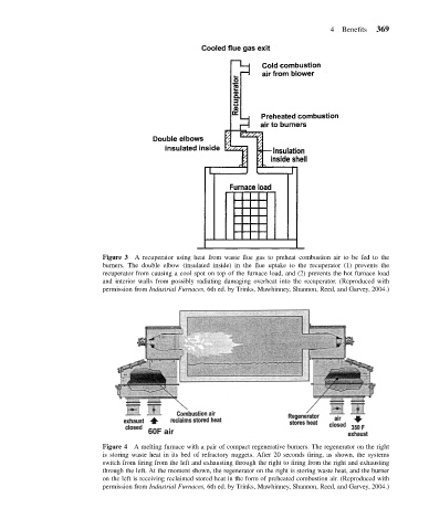
Figure 3 A recuperator using heat from waste flue gas to preheat combustion air to be fed to the
burners. The double elbow (insulated inside) in the flue uptake to the recuperator (1) prevents the
recuperator from causing a cool spot on top of the furnace load, and (2) prevents the hot furnace load
and interior walls from possibly radiating damaging overheat into the recuperator. (Reproduced with
permission from Industrial Furnaces, 6th ed. by Trinks, Mawhinney, Shannon, Reed, and Garvey, 2004.)
Figure 4 A melting furnace with a pair of compact regenerative burners. The regenerator on the right
is storing waste heat in its bed of refractory nuggets. After 20 seconds firing, as shown, the systems
switch from firing from the left and exhausting through the right to firing from the right and exhausting
through the left. At the moment shown, the regenerator on the right is storing waste heat, and the burner
on the left is receiving reclaimed stored heat in the form of preheated combustion air. (Reproduced with
permission from Industrial Furnaces, 6th ed. by Trinks, Mawhinney, Shannon, Reed, and Garvey, 2004.)