
Page 523 - Mechanical Engineers' Handbook (Volume 4)
P. 523
512 Cryogenic Systems
generally increases by 3 to 5%/year. Nitrogen is widely used for inert atmosphere generation
in the metals, electronics and semiconductor, and chemical industries, and as a source of
deep refrigeration, especially for food freezing and transporation. Oxygen is used in the steel
industry for blast furnace air enrichment, for welding and scarfing, and for alloying operation.
It is also used in the chemical industry in oxidation steps, for wastewater treatment, for
welding and cutting, and for breathing. Argon, mainly used in welding, in stainless steel
making, and in the production of specialized inert atmospheres, has a demand of only about
2% of that of oxygen. However, this represents about 25% of the value of oxygen shipments,
and the argon demand is growing faster than that of oxygen or nitrogen.
Since all of the industrial gases are expensive to ship long distances, the industry was
developed by locating a large number of plants close to markets and sized to meet nearby
market demand. Maximum oxygen plant size has now grown into the 3000 ton/day range,
but these plants are also located close to the consumer with the product delivered by pipe
line. Use contracts are often long-term take-or-pay rental arrangements.
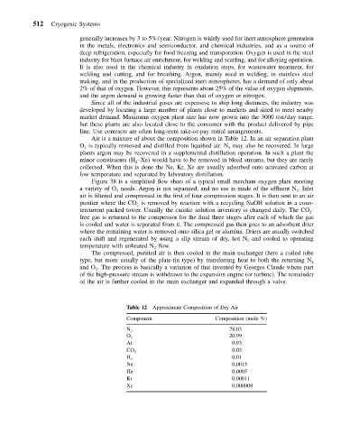
Air is a mixture of about the composition shown in Table 12. In an air separation plant
O is typically removed and distilled from liquified air. N may also be recovered. In large
2
2
plants argon may be recovered in a supplemental distillation operation. In such a plant the
minor constituents (H –Xe) would have to be removed in bleed streams, but they are rarely
2
collected. When this is done the Ne, Kr, Xe are usually adsorbed onto activated carbon at
low temperature and separated by laboratory distillation.
Figure 38 is a simplified flow sheet of a typical small merchant oxygen plant meeting
a variety of O needs. Argon is not separated, and no use is made of the effluent N . Inlet
2
2
air is filtered and compressed in the first of four compression stages. It is then sent to an air
purifier where the CO is removed by reaction with a recycling NaOH solution in a coun-
2
tercurrent packed tower. Usually the caustic solution inventory is changed daily. The CO -
2
free gas is returned to the compressor for the final three stages after each of which the gas
is cooled and water is separated from it. The compressed gas then goes to an adsorbent drier
where the remaining water is removed onto silica gel or alumina. Driers are usually switched
each shift and regenerated by using a slip stream of dry, hot N and cooled to operating
2
temperature with unheated N flow.
2
The compressed, purified air is then cooled in the main exchanger (here a coiled tube
type, but more usually of the plate-fin type) by transferring heat to both the returning N 2
and O . The process is basically a variation of that invented by Georges Claude where part
2
of the high-pressure stream is withdrawn to the expansion engine (or turbine). The remainder
of the air is further cooled in the main exchanger and expanded through a valve.
Table 12 Approximate Composition of Dry Air
Component Composition (mole %)
78.03
N 2
20.99
O 2
Ar 0.93
0.03
CO 2
0.01
H 2
Ne 0.0015
He 0.0005
Kr 0.00011
Xe 0.000008