
Page 68 - Mechanical Engineers' Handbook (Volume 4)
P. 68
4 Fluid Kinematics 57
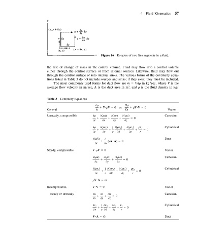
Figure 16 Rotation of two line segments in a fluid.
the rate of change of mass in the control volume. Fluid may flow into a control volume
either through the control surface or from internal sources. Likewise, fluid may flow out
through the control surface or into internal sinks. The various forms of the continuity equa-
tions listed in Table 3 do not include sources and sinks; if they exist, they must be included.
The most commonly used forms for duct flow are m VA in kg/sec, where V is the
˙
3
average flow velocity in m/sec, A is the duct area in m , and is the fluid density in kg/
Table 3 Continuity Equations
D
V 0or V 0
General t Dt Vector
Unsteady, compressible ( u) ( v) ( w) Cartesian
0
t x y z
( v ) 1 ( v ) ( v ) v r Cylindrical
z
r
0
t r r
z r
( A) Duct
( V A) 0
t s
Steady, compressible V 0 Vector
( u) ( v) ( w) Cartesian
0
x y z
( v ) 1 ( v ) ( v ) v r Cylindrical
r
z
0
r r
z r
V A ˙m
Incompressible, V 0 Vector
steady or unsteady u v w Cartesian
0
x y z
v r 1 v
v z v r Cylindrical
0
r r
z r
V A Q Duct