
Page 56 - Singiresu S. Rao-Mechanical Vibrations in SI Units, Global Edition-Pearson (2017)
P. 56
1.7 sprinG elements 53
1.7.1 Most springs used in practical systems exhibit a nonlinear force-deflection relation,
nonlinear particularly when the deflections are large. If a nonlinear spring undergoes small deflec-
springs tions, it can be replaced by a linear spring by using the procedure discussed in Section 1.7.2.
In vibration analysis, nonlinear springs whose force-deflection relations are given by
3
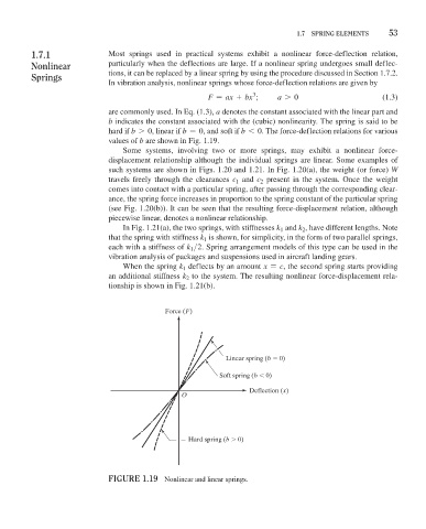
F = ax + bx ; a 7 0 (1.3)
are commonly used. In Eq. (1.3), a denotes the constant associated with the linear part and
b indicates the constant associated with the (cubic) nonlinearity. The spring is said to be
hard if b 7 0, linear if b = 0, and soft if b 6 0. The force-deflection relations for various
values of b are shown in Fig. 1.19.
Some systems, involving two or more springs, may exhibit a nonlinear force-
displacement relationship although the individual springs are linear. Some examples of
such systems are shown in Figs. 1.20 and 1.21. In Fig. 1.20(a), the weight (or force) W
travels freely through the clearances c and c present in the system. Once the weight
1
2
comes into contact with a particular spring, after passing through the corresponding clear-
ance, the spring force increases in proportion to the spring constant of the particular spring
(see Fig. 1.20(b)). It can be seen that the resulting force-displacement relation, although
piecewise linear, denotes a nonlinear relationship.
In Fig. 1.21(a), the two springs, with stiffnesses k and k , have different lengths. Note
1
2
that the spring with stiffness k is shown, for simplicity, in the form of two parallel springs,
1
each with a stiffness of k >2. Spring arrangement models of this type can be used in the
1
vibration analysis of packages and suspensions used in aircraft landing gears.
When the spring k deflects by an amount x = c, the second spring starts providing
1
an additional stiffness k to the system. The resulting nonlinear force-displacement rela-
2
tionship is shown in Fig. 1.21(b).
Force (F)
Linear spring (b 0)
Soft spring (b 0)
Deflection (x)
O
Hard spring (b 0)
FiGure 1.19 Nonlinear and linear springs.