
Page 70 - Singiresu S. Rao-Mechanical Vibrations in SI Units, Global Edition-Pearson (2017)
P. 70
1.7 sprinG elements 67
C x x
F F C
x 2
B B
k x B
2 2
k 2 k 2 F
l
u x D
l 2 x 1 l 3
k x A
1 1
k 1 A k 1 A
l 1 l 1 l 2
O O
(a) (b) (c)
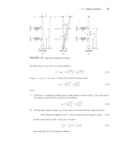
FiGure 1.33 Rigid bar connected by springs.
By expressing F as k eq x, Eq. (E.1) can be written as
x 1 l 1 x 2 l 2
F = k eq x = k 1 ¢ ≤ + k 2 ¢ ≤ (E.2)
l l
Using x 1 = l 1 u, x 2 = l 2 u, and x = lu, Eq. (E.2) yields the desired result:
2 2
l 1 l 2
k eq = k 1 ¢ ≤ + k 2 ¢ ≤ (E.3)
l l
Notes:
1. If the force F is applied at another point D of the rigid bar as shown in Fig. 1.33(c), the equiva-
lent spring constant referred to point D can be found as
2 2
l 1 l 2
k eq = k 1 ¢ ≤ + k 2 ¢ ≤ (E.4)
l 3 l 3
2. The equivalent spring constant, k eq , of the system can also be found by using the relation:
Work done by the applied force F = Strain energy stored in springs k 1 and k 2 (E.5)
For the system shown in Fig. 1.33(a), Eq. (E.5) gives
1 1 1
2
Fx = k 1 x 1 + k 2 x 2 2 (E.6)
2 2 2
from which Eq. (E.3) can readily be obtained.