
Page 78 - Singiresu S. Rao-Mechanical Vibrations in SI Units, Global Edition-Pearson (2017)
P. 78
1.9 dampinG elements 75
include (1) fluid film between sliding surfaces, (2) fluid flow around a piston in a cylinder,
(3) fluid flow through an orifice, and (4) fluid film around a journal in a bearing.
Coulomb or Dry-Friction Damping. Here the damping force is constant in magnitude
but opposite in direction to that of the motion of the vibrating body. It is caused by friction
between rubbing surfaces that either are dry or have insufficient lubrication.
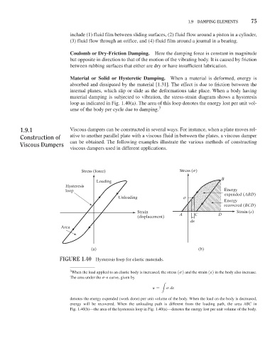
Material or Solid or Hysteretic Damping. When a material is deformed, energy is
absorbed and dissipated by the material [1.31]. The effect is due to friction between the
internal planes, which slip or slide as the deformations take place. When a body having
material damping is subjected to vibration, the stress-strain diagram shows a hysteresis
loop as indicated in Fig. 1.40(a). The area of this loop denotes the energy lost per unit vol-
ume of the body per cycle due to damping. 3
1.9.1 Viscous dampers can be constructed in several ways. For instance, when a plate moves rel-
Construction of ative to another parallel plate with a viscous fluid in between the plates, a viscous damper
Viscous dampers can be obtained. The following examples illustrate the various methods of constructing
viscous dampers used in different applications.
Stress (force) Stress (s)
B
Loading
Hysteresis
loop Energy
Unloading s expended (ABD)
Energy
recovered (BCD)
Strain Strain (e)
(displacement) A C D
de
Area
(a) (b)
FiGure 1.40 Hysteresis loop for elastic materials.
3 When the load applied to an elastic body is increased, the stress 1s2 and the strain 1e2 in the body also increase.
The area under the s@e curve, given by
u = s de
L
denotes the energy expended (work done) per unit volume of the body. When the load on the body is decreased,
energy will be recovered. When the unloading path is different from the loading path, the area ABC in
Fig. 1.40(b)—the area of the hysteresis loop in Fig. 1.40(a)—denotes the energy lost per unit volume of the body.