
Page 160 - Mechanics Analysis Composite Materials
P. 160
Chapter 4. Mechanics of a composite layer 145
. ..
20
16
12
a
4
0
o 2 4 6 a io
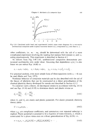
Fig. 4.16. Calculated (solid lines) and experimental (circles) stress-strain diagrams for a two-matrix
unidirectional composite under in-plane transverse tension (~2’). compression (a;) and shear (TI?).
other coefficients, Le., mI “‘~4, should be determined with the aid of a more
complicated experiment involving the loading that induces both stresses a?and 212
acting simultaneously. This experiment is described in Section 4.3.
As follows from Fig. 3.40-3.43, unidirectional composites demonstrate pro-
nounced nonlinearity only under shear. Assuming that dependence E*(o~)is also
linear we can reduce Eqs. (4.60) to
.
3 5
EI =alcl +d102, 82 =b~c~+d~al,yI2 =CIZI~+C~Z~~+C~Z~~
For practical analysis, even more simple form of these equations (with c3 = 0) can
be used (Hahn and Tsai, 1973).
Nonlinear behavior of composite materials can be also described with the aid of
the theory of plasticity that can be constructed as a direct generalization of the
classical plasticity theory developed for metals and described in Section 4.1.2.
To construct such a theory, we decompose strains in accordance with Eq. (4.15)
and use Eqs. (4.16) and (4.18) to determine elastic and plastic strains as
(4.61)
where U, and Up are elastic and plastic potentials. For elastic potential, elasticity
theory yields
U = ci,jk/ai,jak/ , (4.62)
where C;jk/ are compliance coefficients, and summation over repeated subscript is
implied. Plastic potential is assumed to be a function of stress intensity, a, which is
constructed for a plane stress state as a direct generalization of Eq. (4.24), Le.,
(r = ai,jnj.j+ ,/- + Jaiikl,,,,,a;,ak~a,,,,, + ... , (4.63)