
Page 162 - Mechanics Analysis Composite Materials
P. 162
Chapter 4. Mechanics of a composite layer 147
T,?,MPa
140 -
" 3
40
20 -
0 I Yn,%
0 1 2 3 4 5 6 7 0
(b)
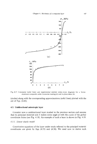
Fig. 4.17. Calculated (solid lines) and experimental (circles) stress-strain diagrams for a boron -
aluminum composite under transverse loading (a) and in-plane shear (b).
(circles) along with the corresponding approximations (solid lines) plotted with the
aid of Eqs. (4.65).
4.3. Unidirectional anisotropic layer
Consider now a unidirectional layer studied in the previous section and assume
that its principal material axis I makes some angle 4 with the x-axis of the global
coordinate frame (see Fig. 4.18). An example of such a layer is shown in Fig. 4.19.
4.3.1. Linear elastic model
Constitutive equations of the layer under study referred to the principal material
coordinates are given by Eqs. (4.55) and (4.56). We need now to derive such