
Page 271 - Mechanics Analysis Composite Materials
P. 271
256 Mechanics and analysis of composite materials
5.11. Example
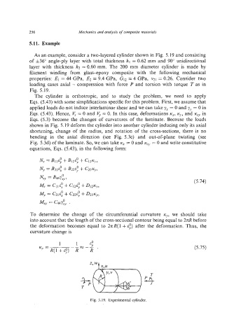
As an example, consider a two-layered cylinder shown in Fig. 5.19 and consisting
of h36" angle-ply layer with total thickness hl = 0.62 mm and 90" unidirectional
layer with thickness h2 = 0.60 mm. The 200 mm diameter cylinder is made by
filament winding from glass+poxy composite with the following mechanical
properties: E1 = 44 GPa, E2 = 9.4 GPa, G12 = 4 GPa, v21 = 0.26. Consider two
loading cases axial - compression with force P and torsion with torque T as in
Fig. 5.19.
The cylinder is orthotropic, and to study the problem, we need to apply
Eqs. (5.43) with some simplifications specific for this problem. First, we assume that
applied loads do not induce interlaminar shear and we can take yx = 0 and yv = 0 in
Eqs. (5.43). Hence, V, = 0 and V, = 0. In this case, deformations IC,, K,,, and K... in
Eqs. (5.3) become the changes of curvatures of the laminate. Because the loads
shown in Fig. 5.19 deform the cylinder into another cyIinder inducing only its axial
shortening, change of the radius, and rotation of the cross-sections, there is no
bending in the axial direction (see Fig. 5.3~)and out-of-plane twisting (see
Fig. 5.3d) of the laminate. So, we can take rcX = 0 and rcrV =0 and write constitutive
equations, Eqs. (5.43), in the following form:
(5.74)
To determine the change of the circumferential curvature IC", we should take
into account that the length of the cross-sectional contour being equal to 2RR before
the deformation becomes equal to 27c R( 1 +8:) after the deformation. Thus, the
curvature change is
(5.75)
Fig. 5.19. Experimental cylinder.