
Page 274 - Mechanics Analysis Composite Materials
P. 274
Chapter 5. Mechanics of laminates 259
Calculation with the aid of Eqs. (5.79) gives
,
$; = -8.1 ~O-~P, = 1.8 x ~O-~P
E;
where P should be substituted in kN. Comparison of the obtained results with
experimental data for the cylinder in Fig. 5.21 is presented in Fig. 5.22.
To determine the stresses, we first use Eqs. (5.69) which, in conjunction with
Eq. (5.75) yield
(5.82)
where 0 < ZI < hl and hl < z2 < hl + h?. Because (hl + h?)/R = 0.0122 for the
cylinder under study, we can neglect zl/R and z?/R in comparison with unity and
write
&(I) = - 0 (5.83)
1' 1' -E,..
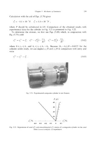
Fig. 5.21. Experimental composite cylinder in test fixtures.
P, kN
E;,% - E;,%
-0.4 -0.3 -0.2 -0.1 0 0.1
Fig. 5.22. Dependence of axial (E:) and circumferential (E!) strains of a composite cylinder on the axial
force: (-) analysis; (oj experiment.