
Page 278 - Mechanics Analysis Composite Materials
P. 278
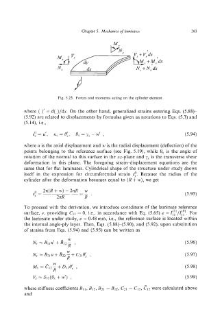
Chapter 5.  Mechanics of laminates           263


                                               PN,,          I

                                                        E+;:dx
                                                         N, +N, dx


                         Fig. 5.25.  Forccs and moments acting on the cylinder element.

           where  ( )’ = d( )/&. On the other hand, generalized strains entering Eqs. (5.88)-
           (5.92) are related to displacements by formulas given as notations to Eqs. (5.3)and
           (5.14),  i.e.,


           where u is the axial displacement and w is the radial displacement (deflection) of the
           points  belonging to the  reference surface (see  Fig. 5.19), while  6,  is the  angle of
           rotation of the normal to this surface in the xz-plane and y.r  is the transverse shear
           deformation  in  this  plane.  The  foregoing  strain-displacement  equations  are  the
           same that for flat laminates. Cylindrical shape of the structure under  study shows
           itself  in  the  expression  for  circumferential  strain  6:.  Because  the  radius  of  the
           cylinder after the deformation  becomes equal to (R + w),we  get

               0   2n(R+w) -2nR     w
               E,.  =             =-                                         (5.95)
                        2d          R‘
           To proceed with the derivation, we introduce coordinate of the laminate reference
                                                                            (0)
                                                                        (1)
           surface, e, providing  CII= 0, i.e.,  in accordance with  Eq. (5.65) e =I,,/I, , . For
           the laminate under study, e = 0.48 mm, i.e.,  the reference surface is located within
           the internal angle-ply layer. Then, Eqs. (5.88)-(5.90),  and (5.92), upon substitution
           of strains from Eqs. (5.94) and (5.95) can be written as
                             W
              IVr=B1~u’+8l2- ,                                               (5.96)
                             R
                            W’
                                      ,
               N,.=B~,U+~~~-+C~,~~                                           (5.97)
                             R
                       W
              A&=CIZ-+DII~:,                                                 (5.98)
                       R
               K = SS5(& +w’),                                               (5.99)
           where stiffness coefficients  BI~,BI~,BZI=B12, C21  = CIZ,c12  were calculated above
           and