
Page 283 - Mechanics Analysis Composite Materials
P. 283
268 Mechanics and analysis of composite materials
T
Nxy=- .
2xR2
Thus,
T
y:v = (5.112)
For the experimental cylinder, shown in Fig. 5.21, normal strains were measured in
the directions making f45" angles with the cylinder meridian. To find these strains,
we can use Eqs. (5.71) with $i = f45", i.e.,
&f -&LO 2Y.xy
45 -
For the cylinder under study with B44 =Zi:) = 9.5 GPa mm and R = IO0mm, we
get
T
E& = f- = f0.84 x 10-6T ,
4d2B44
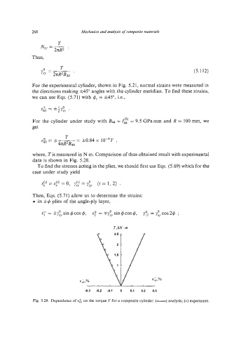
where, Tis measured in N m. Comparison of thus obtained result with experimental
data is shown in Fig. 5.28.
To find the stresses acting in the plies, we should first use Eqs. (5.69) which for the
case under study yield
&t)= (9 = 0 (0
E?, 1 Y,, =Y$ (i= 11 2) .
Then, Eqs. (5.71) allow us to determine the strains:
0 in &q5 plies of the angle-ply layer,
-0.3 -0.2 -0.1 0 0.1 0.2 0.3
Fig. 5.28. Dependence of e& on the torque 7' for a composite cylinder: (-) analysis; (0) experiment.