
Page 288 - Mechanics Analysis Composite Materials
P. 288
Chapter 6. Failure criteria and strength of laminates 273
can be constructed. However, uncertainty and approximate character of the existing
micromechanical models discussed in Section 3.3 result in relatively poor accuracy
of this method which, being in principle rather promising, has not found by now
wide practical application.
The second basic approach that can be referred to as macrophenomenological
one deals with the average stresses 01, 02, and 212 shown in Fig. 6.1 and ignores the
ply microstructure. For a plane stress state of an orthotropic ply, this approach
requires at least five experimental results specifying material strength under:
0 longitudinal tension, a: (point A in Fig. 6.2),
0 longitudinal compression, a,,
0 transverse tension, 5; (point B in Fig. 6.2),
0 transverse compression, 8;,
0 in-plane shear, 212 (point C in Fig. 6.2).
Obviously, these data are not enough to construct the complete failure surface, and
two possible ways leading to two types of failure criteria can be used.
The first type referred to as structural failure criteria involves some assumptions
concerning the possible failure modes that can help us to specify the shape of
the failure surface. According to the second way providing failure criteria of
approximation type, experiments simulating a set of complicated stress states
(such that two or all three stresses 01, 02, and 212 are induced simultaneously) are
undertaken. As a result, a system of points like point D in Fig. 6.2 is determined
and approximated with some suitable surface.
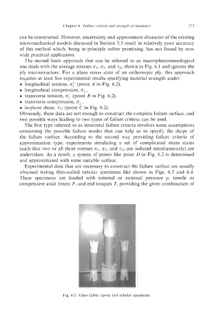
Experimental data that are necessary to construct the failure surface are usually
obtained testing thin-walled tubular specimens like shown in Figs. 6.3 and 6.4.
These specimens are loaded with internal or external pressure p, tensile or
compressive axial forces P, and end torques T, providing the given combination of
I - - , U@l
Fig. 6.3. Glass fabric-epoxy test tubular specimens.