
Page 289 - Mechanics Analysis Composite Materials
P. 289
274 Mechanics and unalysis of composite wzateriuls
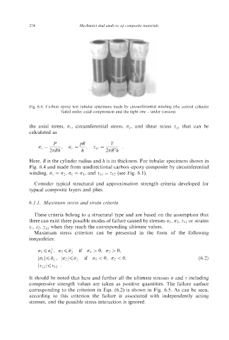
Fig. 6.4. Carbon-epoxy test tubular specimens made by circumferential winding (the central cylinder
failed under axial compression and the right one - under torsion).
the axial stress, o.,., circumferential stress, o,., and shear stress z.yJ that can be
calculated as
P PR T
or = - , =
o,, = - z,,
2nRh ’ 2nR2h
~
Here, R is the cylinder radius and 12 is its thickness. For tubular specimens shown in
Fig. 6.4 and made from unidirectional carbon-epoxy composite by circumferential
winding, ox = 02, o,, = 01, and zxv = 212 (see Fig. 6.1).
Consider typical structural and approximation strength criteria developed for
typical composite layers and plies.
6. I. I. Maximuin stress and strain criteria
These criteria belong to a structural type and are based on the assumption that
there can exist three possible modes of failure caused by stresses 01, 62, 212 or strains
81, E?, yI2 when they reach the corresponding ultimate values.
Maximum stress criterion can be presented in the form of the following
inequalities:
It should be noted that here and further all the ultimate stresses 0 and Z including
compressive strength values are taken as positive quantities. The failure surface
corresponding to the criterion in Eqs. (6.2) is shown in Fig. 6.5. As can be seen,
according to this criterion the failure is associated with independently acting
stresses, and the possible stress interaction is ignored.