
Page 230 - Mechanics of Asphalt Microstructure and Micromechanics
P. 230
222 Ch a p t e r Sev e n
x is the damage parameter; A v is the area of cracks and air voids; S is total cross-sec-
tional area of the specimen; s is the stress applied to the damaged specimen; and s e is
the effective stress applied to the fictitious undamaged specimen.
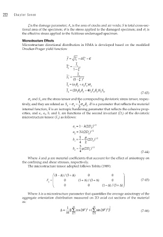
Microstructure Effects
Microstructure directional distribution in HMA is developed based on the modified
Drucker-Prager yield function:
f = J −α I −κ
e
e
2 1
I
I = 1
e
1 − ξ *
1
J
J = 2
e
2 * 2
1 ( − ξ )
I = ( a δ + aF )σ
1 1 ij j 2 ij ij
J = 2( b δδ + 4 b F δ ) S S
2 1 ik jl 2 ik lj ij kl (7-43)
s ij and S ij are the stress tensor and the corresponding deviatoric stress tensor, respec-
1
–
tively, and they are related as S = σ − σ δ . a is a parameter that reflects the material
ij ij kk ij
– 3
internal function, κ is an isotropic hardening parameter that reflects the cohesive prop-
erties, and a 1 , a 2 , b 1 and b 1 are functions of the second invariant (D 2 ) of the deviatoric
microstructure tensor (F ij ) as follows:
/
1
a =− λ( 2 D ) 12
1 2
λ
a = 32 D ) 12
/
(
2 2
1 μ
b = − 2 ( D ) 12
/
1 2
4 2
b b = 3 μ( 2 D ) 12
/
2 4 2 (7-44)
Where l and m are material coefficients that account for the effect of anisotropy on
the confining and shear stresses, respectively.
The microstructure tensor adopted follows Tobita (1989):
⎛ ⎛ (1 Δ + ) 0 0 ⎞
− )/(3 Δ
+ )/(3 Δ
F = ⎜ 0 (1 Δ + ) 0 ⎟ (7-45)
ij ⎜ ⎟
⎜ ⎝ 0 0 (1 Δ + ) ⎟
− )/(3 Δ ⎠
Where Δ is a microstructure parameter that quantifies the average anisotropy of the
aggregate orientation distribution measured on 2D axial cut sections of the material
as:
1 M M 1
Δ= [( ∑ cos 2 )θ k 2 + ( ∑ sin 2 ) ]θ k 2 2 (7-46)
M
k =1 k =1