
Page 69 - Mechanics of Microelectromechanical Systems
P. 69
56 Chapter 1
define the three springs that characterize the lumped-parameter elastic model
of a cantilever, and is further employed in calculating the natural frequencies
of such a structure, the stiffnesses of Eq. (1.16) are the ones to be used when
calculating forces and moments that correspond to known tip deflections and
slopes. The difference between individual (definition) stiffnesses (denoted
with an upper bar, as shown in Eqs. (1.217) – this notation will be used from
this point on) and stiffnesses resulting from inversion of the compliance
matrix (which is unique for a given beam configuration) will become more
evident in Chapter 2 when studying microcantilever applications.
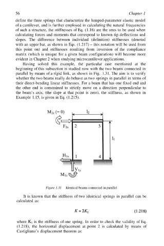
Having solved this example, the particular case mentioned at the
beginning of this subsection is studied now with the two beams connected in
parallel by means of a rigid link, as shown in Fig. 1.31. The aim is to verify
whether the two beams really do behave as two springs in parallel in terms of
their direct-bending linear stiffnesses. For a beam that has one fixed end and
the other end is constrained to strictly move on a direction perpendicular to
the beam’s axis, (the slope at that point is zero), the stiffness, as shown in
Example 1.15, is given in Eq. (1.215).
Figure 1.31 Identical beams connected in parallel
It is known that the stiffness of two identical springs in parallel can be
calculated as:
where is the stiffness of one spring. In order to check the validity of Eq.
(1.218), the horizontal displacement at point 2 is calculated by means of
Castigliano’s displacement theorem as: