
Page 53 - Mechatronic Systems Modelling and Simulation with HDLs
P. 53
42 3 MODELLING AND SIMULATION OF MIXED SYSTEMS
L R
k
F
i i i C
m L R
x
u s i s L R C u s C
b
i
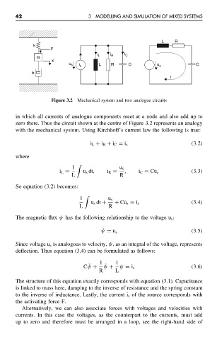
Figure 3.2 Mechanical system and two analogue circuits
in which all currents of analogue components meet at a node and also add up to
zero there. Thus the circuit shown at the centre of Figure 3.2 represents an analogy
with the mechanical system. Using Kirchhoff’s current law the following is true:
i L + i R + i C = i s (3.2)
where
1 u s
i L = u s dt, i R = , i C = C˙u s (3.3)
L R
So equation (3.2) becomes:
1 u s
u s dt + + C˙u s = i s (3.4)
L R
The magnetic flux ψ has the following relationship to the voltage u s :
˙
ψ = u s (3.5)
Since voltage u s is analogous to velocity, ψ, as an integral of the voltage, represents
deflection. Thus equation (3.4) can be formulated as follows:
1 1
¨ ˙
Cψ + ψ + ψ = i s (3.6)
R L
The structure of this equation exactly corresponds with equation (3.1). Capacitance
is linked to mass here, damping to the inverse of resistance and the spring constant
to the inverse of inductance. Lastly, the current i s of the source corresponds with
the activating force F.
Alternatively, we can also associate forces with voltages and velocities with
currents. In this case the voltages, as the counterpart to the currents, must add
up to zero and therefore must be arranged in a loop, see the right-hand side of