
Page 55 - Mechatronics for Safety Security and Dependability in a New Era
P. 55
Ch09-I044963.fm Page 38 Tuesday, July 25, 2006 11:58 AM
Ch09-I044963.fm
38 38 Page 38 Tuesday, July 25,2006 11:58 AM
continuously repeated during propulsion, reported by Veeger et al (1998). Moreover, the propelling
motion in different situation have been researched by Hildebrant et al (1970), who reported the force
required to propel over the slope is larger than the propelling-force on the flat road. As referred to
example above, the wheelchair propulsion has individual autonomic motion that the operator adjusts
each velocity and force. So, the power-assist function is necessary to analyze the quantitative human
characteristics of the human-wheelchair system. However, since many wheelchair researches are still
not summarized much quantitatively, they do not give much good design of this function.
In this research, we propose the system based on the quantitative human-wheelchair system model for
establishing design manual of the power-assist function. The first factor to be considered should be
the influence of propelling force to velocity by inertia, we consider.
METHODS
Model
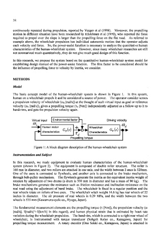
The basic concept model of the human-wheelchair system is shown in Figure 1. In this system,
human on a wheelchair propels it and be considered a source of power. The operator consider senses
a propulsion velocity of wheelchair (<Dd [rad/s]) at the thought of such virtual input as goal or reference
velocity (co s [rad/s]), gives a propelling torque (xd [Nm]) independently adjusted as a follow-up to it to
hand-rims, and gets the propulsion velocity again.
Virtual input Driving velocity
CO.,
Wheelchair
T
Characteristics
Propelling torque
Figure 1: A block diagram description of the human-wheelchair system
Instrumentation and Subject
In this research, we made equipment to evaluate human characteristics of the human-wheelchair
system (shown in Figure 2). The equipment is composed of double roller structure. The roller is
160 mm in diameter, and two rollers are attached in one axis, and the width between 2 axes is 320mm.
One of the axes is connected to flywheels, and another axis is connected to the brake mechanism,
through belt-pulley mechanism. The flywheels generate the inertia as the equivalent inertia weight of
rotation by adjustment of two drums (a drum is 330 mm in diameter and has a mass of 80 kg). The
brake mechanisms generate the resistance such as friction resistance and inclination resistance on the
real road using the adjustment of band brake. The wheelchair is fixed in a regular position and the
rear wheels rotate on rollers of two axes. The wheelchair witch weight 14.6 kg has rear wheels of 22
inches in diameter. The air pressure of real wheels is 0.29 MPa, and the width between the two
wheels is 535 mm (Kawamura-cycle co., Hyogo, Japan).
The fundamental measurement elements are the propelling torque (x [Nm]), the propulsion velocity (co
[rad/s], 1 [rad/s] ^ 1 [km/h] in this regard), and human physical strain that is estimated by heart rate
variation during the wheelchair propulsion. The hand-rim, which is connected to a right rear wheel of
wheelchair, is instrumented with torque transducer (Sohgoh Keiso co., Kanagawa, Japan) for
propelling torque measurement. A rotary encoder (Ono Sokki co., Kanagawa, Japan) is attached in