
Page 131 - Mechatronics for Safety, Security and Dependability in a New Era
P. 131
Ch24-I044963.fm Page 115 Monday, August 7, 2006 11:27 AM
Monday, August 7,2006
Page 115
Ch24-I044963.fm
11:27 AM
115
115
on for individual features [2].
(a) (b) Face 1 1
F a c e
(b)
Face 2
(c)
(c)
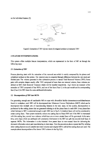
Figure2: Extraction of TRV (a) raw stock (b) resigned product (c) extracted TRV
3 FEATURE INTERPRETATIONS
This system offers multiple feature interpretations, which are represented in the form of MF st through the
following steps:
3.1 Extraction of TRV
Process planning starts with the extraction of the removal area which is mainly composed by the planes and
cylindrical surfaces in this system. The removal area is computed through difference between the raw stock and
finished part. The volume generated in this subtraction process is named Total Removal Volume (TRV). Some
parts with complex shapes usually offer TRV composed of more than one removal volume, these volumes are
defined as SRV (Sub Removal Volumes) which will be handled respectively. Fig.2 shows an example of the
extraction of TRV composed of four SRVs, and one of the iaces (Face 1) in the part model and its corresponding
face (Face 2) in TRV share the same attributed infbrmatioa
3.2 Decomposition ofTRVinto MCPs
For generating enough sets of machinable MFs to cope with diversified facility circumstances and disturbances
found in workplace, each SRV will be decomposed into Minimum Convex Polyhedrons (MCP) which can be
recomposed into multiple sets of manufacturing features in the next steps. In this system, decomposition is
performed by the cutting planes that are generated referring to all the planar faces in each SRV. Every planar face
which belongs to SRV is extended enough to split SRV (as in Fig.3). Cylindrical faces will not be considered to
create cutting faces. Then system randomly selects one cutting face to bisect SRV and if the SRV is intersected
with this cutting face, several new volumes which have one or more created faces will be generated. At the same
time, some faces which are attributed with constraints information in the SRV are split into several small iaces in
separate MCPs. The information is to be inherited from parent laces to new-created faces for delivering the
demands information about part manufacturing to later steps. Then the procedures above repeats itself by utilizing
other cutting facesto cut all cuttable new-born volumes and original SRVs until all the cutting faces are used The
example about decomposition of the former TRV is shown in the Fig.3 (b).