
Page 127 - Mechatronics for Safety, Security and Dependability in a New Era
P. 127
Ch23-I044963.fm Page 111 Tuesday, August 1, 2006 9:09 PM
9:09 PM
Tuesday, August
Page 111
Ch23-I044963.fm
1, 2006
111
111
fixed for tool diameter and high speed milling. It is avoidable, and is still worthwhile to develop a
better way of obviation. Upon realization of the fact that uncut regions exist if there is an intersection
between a previous tool envelope and a current tool envelope, the ODM is extended to the uncut
region detection and clean up curve generation based on the TLE concept, which enables the ODM to
be easily applied to uncut region detection. The method, namely the extended ODM, is proposed by
shifting the object of ODM from OLEs to TLEs.
To verify the extended ODM, the entire process of uncut region detection and clean up curve
generation is evaluated through an illustrated example shown in Fig.2. Figure 2(a) shows the previous
th
th
[(n-l) ] tool path, the current [(n) ] tool path, the inward trajectory made by the previous tool path
(previous TLE), and the outward trajectory made by the current tool path (current TLE). By taking a
glance at Fig.2(a), we easily notice that the uncut region exists if there is an intersection between
previous TLE and current TLE. Moreover, by imaging that the previous tool path to be like a pocket
CLE and the current tool path to be like an island CLE, the previous TLE may be considered as a
pocket OLE and current TLE may be considered as an island OLE, and then, we could see that those
exactly match as shown in Fig.2(b). Therefore, we just need to carry out the ODM to detect the uncut
regions upon OLE/TLE concepts. After the previous/current TLEs construction, the TLE
reconstruction is processed as we did in the offset curve generation of the pocket with one island in
Fig.l. Then, non-intersecting simple TLEs are obtained as shown in Fig.2(c). Performing TLE
validation with the rule that the characteristic of the previous TLE is transferred to the combined TLE
when a previous TLE and a current TLE are composed into a TLE, four simple TLEs with clockwise
orientation are discarded. Finally, four valid TLEs corresponding to the boundaries of uncut regions
are kept to play the role of the clean up curve. The clean up curves are then appended to current valid
OLEs taking the shortest line segment for the construction of an uncut free tool path, as shown in
Fig.2(d). Here, we may conclude that the extended ODM is flexible and robust enough to generate
offset curves for uncut free pocket machining with islands.
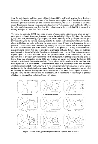
(a) Boundary of pocket (b) Local and glol (c) Dissection at
(d) OLE with glob; (c) OLE without intersection
(g) Simple OLEs from pocket and island (h) Combined OLLs without intersection (i) Offset curve for pocket with island
Figure 1: Offset curve generation procedures for a pocket with an island