
Page 206 - Mechatronics for Safety, Security and Dependability in a New Era
P. 206
Ch40-I044963.fm Page 190 Tuesday, August 1, 2006 8:21 PM
Ch40-I044963.fm
190
190 Page 190 Tuesday, August 1, 2006 8:21 PM
DESIGN AND CONFIGURATION OF SDR-4X11
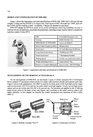
Figure 1 shows the appearance and basic specifications of SDR-4XII. SDR-4XI1 is 58 [cm] tall and
weights 7.0 [kg], and has 28 DOF in its major joints. Each leg has 6 DOF, the trunk has 2 DOF, each arm
has 5 DOF and the neck has 4 DOF. In addition, 5 fingers are attached to each hand.
SDR-4X1I adopts the OPEN-R system as its control architecture which has scalability not only in
software but also in hardware, and adopts the proprietary operating system Aperios which is suitable for
real-time control (Fujita 1997).
CPU 64 bit RISC Processor ( x 3)
Memory 64MB DRAM { x 3)
Operating Sys. & Architecture Aperios & OPEN-R
Robot Control Supplying Media Memory Stick
Input/Output PC Card Slot (Type II)/MS Slot
Image Input (color/stereo) 110,000 pixels CCD
Sound Input/output 7 Microphones/Speaker
Walking Speed 6m/min. max (unleveled surface)
Weight (including battery) Approximately 7Kg
Dimensions (height/width/depth) Approximately 580/270/190mm
Figure 1: Appearance and basic specifications of SDR-4XII
DEVELOPMENT OF THE ROBOTIC ACTUATOR ISA-4
For the development of SDR-4XII, we developed 3 types of robotic actuators ISA-4 (Intelligent
th
Servo Actuator 4 prototype) which consist of a motor with electrical circuits and a precise gear unit.
Figure 2 shows their appearances. ISA-4MH is used for the body parts which need high-power output
such as knee joints, 1SA-4S is used for the parts which need high angular velocity but not high power
output such as arm joints, and ISA-4M is for general use. The actuators are applied to the 22 driving
joints except joints in the head, wrists, and fingers, and contribute to the robot's motion control and
safety operation. In this chapter we describe the control mechanism and functions of ISA-4 (Iribe
2004-1).
ISA-4MH Power
Module
ISA-4M Control' Communication
Module Module
Figure 2: Robotic Actuator "ISA-4" Figure 3: Construction of ISA-4