
Page 322 - Mechatronics for Safety, Security and Dependability in a New Era
P. 322
Ch62-I044963.fm Page 306 Thursday, July 27, 2006 12:06 PM
Ch62-I044963.fm
306
306 Page 306 Thursday, July 27, 2006 12:06 PM
minimized by the use of a frequency-hopping spread-spectrum transmission scheme (Bravo-Escos
2002). Bluetooth profiles, which are defined in the Bluetooth specification, describe how a particular
application can be implemented, and which parts of the core Bluetooth protocol should be used to
support the profile (Bray 2001). In a headset application only a fraction of the capabilities of Bluetooth
is utilized. The Bluetooth audio connection between a cellular phone and a headset can be realized by
using either the headset- or handsfree- profile. To operate with all Bluetooth mobile phones, the
headset must support both profiles. Nowadays there are several kinds of Bluetooth chips and modules
available from various manufacturers. Many of the off-the-shelf modules adapt themselves directly to
headset-type applications.
THE CONSTRUCTED PROTOTYPE
A prototype of a Bluetooth hearing protector was constructed. The prototype PCB includes an
Avantwave BTR110B v0.2 class 2 Bluetooth transceiver module, a number of additional electronics
and a microstrip inverted F-antenna (IFA).
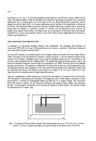
An inverted-F antenna is a compact antenna with a height of about one tenth of the wavelength (Olmos
2002). The layout of the developed IFA antenna is shown in Figure 1. The IF A antenna consists of two
sections: the inverted-L radiating section (a-b-c) and the matching section (b-d-e). The antenna is fed
at point a and grounded at point e (Olmos 2002). The smaller the spacing between points a and e, the
lower the resonance frequency and the higher the impedance (Ali 2000). The final layout was obtained
through trial and error. The antenna is connected to the Bluetooth module by a 50 Q transmission line.
The designed antenna was integrated on the same printed circuit board as the Bluetooth module and
the additional electronics. The printed circuit board has a length of 35 mm and a width of 31 mm.
Thus, the device is relatively easy to install inside the earcup.
There are loudspeakers in both earcups and a single boom microphone is located in front of the mouth.
The microphone is directional and insensitive to background noise, which makes it practical in noisy
environments. A lithium-ion rechargeable battery provides the 3.6 V supply voltage. The Avantwave
BTR110B module includes all the Bluetooth software, and supports both headset and handsfree
profiles. The prototype is compatible with virtually any Bluetooth cellular phone. The module is based
on CSR BlueCore2™ Flash -chip.
Fig. 1. The layout of the inverted F-antenna. The measurements were d-c = 24,5 mm, d-b = 5.0 mm
and a-b = 6.8 mm. The grey area depicts the ground plane on the bottom side of the PCB.