
Page 323 - Mechatronics for Safety, Security and Dependability in a New Era
P. 323
Ch62-I044963.fm Page 307 Thursday, July 27, 2006 12:06 PM
Page 307
Thursday, July 27, 2006
12:06 PM
Ch62-I044963.fm
307
307
THE MEASUREMENTS
Performance of the developed antenna was measured. The reflection coefficient of the antenna was
measured, and the antenna was fine-tuned on the basis of this. The radiation patterns were measured in
all three directions. Finally, the antenna was integrated on the same PCB as the Bluetooth module and
the device was tested with three different GSM cellular phones.
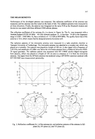
The reflection coefficient of the antenna (Sn) is shown in Figure 2a. The Sn was measured with a
Hewlett Packard 8722D 50 MHz - 40 GHz network analyser. Sn is less than -10 dB in the frequency
range of 2320 - 2560 MHz. S n has a minimum of-12.5 dB at 2450 MHz. The quality factor (Q) of the
antenna is 10.4, which means that the designed antenna functions well.
The radiation patterns of the microstrip antenna were measured in a radio anechoic chamber at
Tampere University of Technology. The microstrip antenna was attached to a wooden rod, which was
placed on a turntable. The antenna was placed at a height of 120 cm. A sine signal with a frequency of
2.45 GHz and amplitude of 0 dBm was fed to the microstrip antenna from a Rohde & Schwartz SMR-
20 signal generator. The radiation pattern was measured with HP 11966E double-ridged waveguide
horn antenna, which was placed at a height of 120 cm and at a distance of 3 m from the microstrip
antenna. The signal from the HP horn antenna was analysed using a HP 8539A spectrum analyser with
85712D EMC auto-measurement personality.
a) 40
—-* 6 0
^
..30
/ X" \ 3 0
10/'"
!" 6 1 rfii \
^ ;—
-10 ) I
-12
/330
2.2 2.4 2.6 2.8
F/GHz 'loo
c) d) 9 °_40^
<:—
15' 150/ -.20 ,/' 30
10/' x
""/-.^
• " ' \ - \
1 5l"l »
L5U 'j
Xj
)
s j •" ' " " •
.,V''
21 530
270
Fig. 2. Reflection coefficient (Sn) of the antenna (a), and radiation patterns of the antenna in XZ-
plane (b), XY-plane (c), and YZ-plane (d).