
Page 328 - Mechatronics for Safety, Security and Dependability in a New Era
P. 328
Ch63-I044963.fm Page 312 Thursday, July 27, 2006 12:08 PM
Ch63-I044963.fm
312
312 Page 312 Thursday, July 27, 2006 12:08 PM
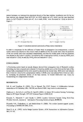
station increases, we increased the placement density of the base stations. Installation area for the six
2
base stations was changed from (a) 15x20 [m] (0.02 station per in ), which was the case described
2
above, to (b)7x7[m](0.12 station per m ). As a result, RMS_ error decreased to 1.3[m] as shown in
Figure 3.
1 W i ^
:Base stations
#5 #4 #:
H E g : actual position
• : calculated position
—-5--
3
3
1
3 13 i.
1
(a) 15X20 [m](0.02[/m]) (b)7X7[m](0.12[/m])
Figure 3: Calculated position and density of base station installation
In order to compensate for the influence of human body on propagation loss measurement, a second
mobile station was attached on the wearer's back in addition to the one on the front. First, the positions
of the two mobile units were calculated independently, and then the middle point of the two positions
was adopted as the worker's position. Incorporating this compensation method, in area (a), RMS_error
was reduced to 2.3[m]. In area (b), RMS_error was reduced to 1.2[m].
CONCLUSIONS
1) Positioning system based on pseudo distance derived from propagation loss of Bluetooth wireless
technology has been proposed and evaluated. 2) Attaching mobile units on the front and the back of the
human body compensated for the error caused by absorption by human body. RMS-error wad reduced
from 3.4[m] to 1.3[m] by this compensation method. 3) RMS_error was reduced from 3.4[m] to 2.3[m]
by increasing the placement density of the base stations. 4) Overall RMS-error was 1.2[m] by
incorporating two compensation methods.
REFERENCES
Fall, K. and Varadhan, K. (2001). The ns Manual, The VINT Project, A Collaboration between
researchers at UC Berkeley, LBL, USC/ISI, and Xerox PARC, http://www.isi.edu/nsnam/ns/.
Hightower J., Bordello G. and Want R. SpotON (2000): An Indoor 3D Location Sensing Technology
Based on RF Signal Strength. UWCSE Technical Report #2000-02-02.
Kitasuka T., Nakanishi T. and Fukuda A. (2003) Location Estimation System Using Multi-Hop
Wireless Network. Journal of Information Processing Society of Japan, 44:SIG10.
Priyantha N.B., Chakraborty A. and Balakrishnan H. (2000). The cricket location-support system.
Proceedings ofMOBICOM2000, 32-43.
Want R. et. al.. (1992). Active Badge Location System. ACM Transactions on Information Systems,
10:1,91-102.