
Page 180 - A Practical Guide from Design Planning to Manufacturing
P. 180
Microarchitecture 153
Each computer architecture defines some finite number of registers
that instructions use to read and write results. To keep instruction size and
code size to a minimum, older architectures tended to define a relatively
small number of registers. This made sense at the time, especially since
manufacturing processes were not capable of creating processors with
large numbers of registers. As a result of having very few architectural
registers to choose from, programs tend to reuse registers after only a
few instructions. This reuse creates false dependencies. True depend-
encies are when a register is read by one instruction after being writ-
ten by another. This is a read-after-write (RAW) dependency. False
dependencies are write-after-read (WAR) or write-after-write (WAW)
dependencies. A write-after-read dependency causes one instruction to
have to wait to write a register until another instruction has read the
value. In a write-after-write dependency, two instructions conflict with
each other by both trying to write the same register. In code without
branches WAW dependencies would not happen because at least one
instruction would always read a result after it was written, but with
branches or interrupts, programs may write the same register more
than once without any reads.
Register renaming removes false dependencies by mapping the archi-
tectural registers of the program code into physical registers on the
processor. The number of physical registers can be greater than the
number of architectural registers, allowing registers to be reused less
often. Eliminating false dependencies makes possible more instruction
reordering and therefore more performance. An on-die register alias
table (RAT) can be used to record which physical register each archi-
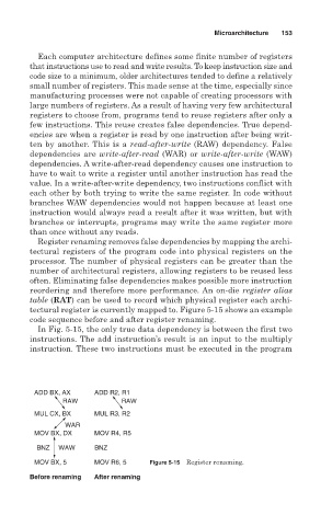
tectural register is currently mapped to. Figure 5-15 shows an example
code sequence before and after register renaming.
In Fig. 5-15, the only true data dependency is between the first two
instructions. The add instruction’s result is an input to the multiply
instruction. These two instructions must be executed in the program
ADD BX, AX ADD R2, R1
RAW RAW
MUL CX, BX MUL R3, R2
WAR
MOV BX, DX MOV R4, R5
BNZ WAW BNZ
MOV BX, 5 MOV R6, 5 Figure 5-15 Register renaming.
Before renaming After renaming