
Page 117 - Microtectonics
P. 117
4.4 · Lattice-Preferred Orientation (LPO) 105
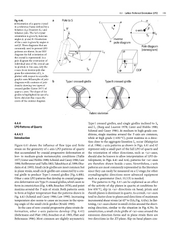
Fig. 4.40.
a Orientation of a quartz crystal
in a reference frame defined by a
foliation (S ), lineation (L ) and
r
r
foliation pole. The full crystal
orientation is given by Eulerian
angles φ, ψ and θ. Orientation
of the c-axis is given by angles α
and β. Three diagrams that are
commonly used to present LPO
patterns are shown. In an ODF
diagram the full orientation of
the crystal is represented. In a
pole diagram the orientation of
individual axes of the crystal can
be plotted; in this case, only the
c-axis. In an inverse-pole dia-
gram the orientation of L is
r
plotted with respect to crystallo-
graphic axes. b Examples of pole
diagrams with contours of pole
density showing two types of
crossed girdles (Lister 1977) of
quartz c-axes. The shape of the
girdles is highlighted by use of a
fabric skeleton that traces the
crests of the contour diagram
4.4.4 Type I crossed girdles, and single girdles inclined to S
r
LPO Patterns of Quartz and L (Burg and Laurent 1978; Lister and Hobbs 1980;
r
Schmid and Casey 1986). At medium to high-grade con-
4.4.4.1 ditions, single maxima around the Y-axis are common,
Introduction while at high grade (>650 °C), point maxima in a direc-
tion close to the aggregate lineation L occur (Mainprice
r
Figure 4.41 shows the influence of flow type and finite et al. 1986). c-axis patterns as shown in Figs. 4.41 and 42
strain on the geometry of c-axis LPO patterns of quartz represent only a small part of the full LPO of quartz and
that accumulated by coaxial progressive deformation at the orientation of other directions, such as <a>-axes,
low- to medium-grade metamorphic conditions (Tullis should also be known to allow interpretation of LPO de-
1977; Lister and Hobbs 1980; Schmid and Casey 1986; Law velopment; in Figs. 4.41 and 4.42, patterns for <a>-axes
1990; Heilbronner and Tullis 2002; Takeshita et al. 1999; Oku- are therefore shown beside c-axes. Nevertheless, c-axis
daira et al. 1995). Small circle girdles are most common but patterns are most commonly represented in the literature
in plane strain, small circle girdles are connected by a cen- since they can easily be measured on a U-stage; for other
tral girdle to produce Type I crossed girdles (Fig. 4.40b). crystallographic directions more advanced equipment
Other c-axis LPO patterns that develop in coaxial progres- such as a goniometer (Sect. 10.3.5) is needed.
sive deformation are Type II crossed girdles, which seem to The patterns in Fig. 4.41 can be explained as an effect
form in constriction (Fig. 4.40b; Bouchez 1978), and point of the activity of slip planes in quartz; at conditions be-
maxima around the Y-axis of strain. Both patterns seem low 650 °C, slip in <a> directions on basal, prism and
to form at higher temperature than the patterns shown in rhomb planes is dominant in quartz. As a result, <a>-axes
Fig. 4.41 (Schmid and Casey 1986; Law 1990). Increasing tend to cluster close to planes and directions of maximum
temperature also seems to cause an increase in the open- incremental shear strain (at 45° to ISA; Fig. 4.43a). In flat-
ing angle of the small circle girdles (Kruhl 1998). tening, <a>-axes cluster in small circles around the short-
In the case of non-coaxial progressive plane strain de- ening direction, similar to the situation in Fig. 4.39c. In
formation, other c-axis patterns develop (Fig. 4.42) constriction, a small circle girdle of <a>-axes around the
(Behrmann and Platt 1982; Bouchez et al. 1983; Platt and extension direction forms and in plane strain there are
Behrmann 1986). Most common are slightly asymmetric two directions in the XY-plane. Slip on basal planes con-